You’re staring at a drywall stud wall with a jumble of marks, wondering which layout marks are actually accurate. You’ve paused, measured, re-measured, and still can’t trust whether holes will line up with the electrical box or bracket. Most people assume digital overlays are “close enough” or rely solely on tape measures, which leads to wasted time and misdrilled holes.
This piece will show you how augmented reality plus LiDAR, RGB, and IMU data turns layout into a millimeter‑accurate process, how to place and verify virtual anchors against a tape or 3‑ft straightedge, and how to export coordinates to Revit/AutoCAD for approvals and audits.
You’ll get step‑by‑step setup, verification checks, and simple ROI calculations. It’s easier than it looks.
Key Takeaways
If you’ve ever struggled to get wall layouts right, this will help.
Real-time AR overlays matter because they cut measurement errors and speed up installs. Imagine you’re hanging a row of cabinets: the app shows exact placement and scale as you move your phone, so you avoid re-drilling holes. How to use it:
- Scan the wall with your phone.
- Tap to place the virtual cabinet, then pinch to scale until the on-screen width reads the cabinet model (e.g., 900 mm).
- Lock the overlay and mark anchor points on the wall.
Tip: aim for placements that show a green alignment line; that means under 5 mm offset.
Sensor fusion (LiDAR + RGB + IMU) gives you stable, millimeter-accurate wall meshes because it combines depth, color, and motion data. Picture remodeling a bathroom where wall flatness matters for tile: the fused mesh shows every bump and bow to 1–3 mm so you can plan shims. How to verify:
- Do a slow, clockwise scan of the room about 1–1.5 meters from the wall.
- Check the mesh error map; red zones mean >3 mm deviation.
- Re-scan any red zones from two angles until they drop below 3 mm.
Pro tip: keep ambient light steady to reduce RGB noise.
Interactive material and lighting toggles help you preview finishes and glare under real conditions because they simulate how surfaces react to your room’s light. Think of choosing a glossy paint for a hallway: toggling glare shows if the finish will reflect a window at noon and create hotspots. How to use them:
- Capture the room lighting with an HDR scan.
- Try finishes (matte, satin, glossy) and note reflected highlights.
- If glare appears near a light source, swap to a lower-gloss finish and re-preview.
One concrete result: switching from glossy to satin cut reflected hotspots by about 60% in a sunlit corridor.
Anchored AR markups and recorded anchor coordinates speed installation and verification because the marks stay tied to real-world points. Imagine installing a lighting rail: you export anchor coordinates to a layout PDF so the electrician drills exactly where the AR marked. How to proceed:
- Place anchors on structural points (studs, corners) in the AR view.
- Export coordinates as a CSV or PDF with reference photos.
- On site, use a laser locator or a measuring tape to confirm anchors within 5 mm.
Note: include a timestamped photo with each anchor for audit trails.
Integrated calibration logs and pre/post scans enforce accuracy thresholds and create audit-ready records because they document device health and final results. Picture a contractor who must prove tolerances for a client: the app’s calibration log shows device status, and pre/post scans show the as-built condition to ±3 mm. Steps to follow:
- Run the built-in calibration routine before each job and save the log.
- Do a quick pre-scan, perform your work, then do a post-scan.
- Attach both scans and the calibration log to the job file for client review.
Result: you’ll have timestamped evidence that measurements met the specified tolerance.
Common Wall-Layout Pain Points: And How AR Fixes Them Now
If you’ve ever started a wall layout from paper measurements, this is why mistakes show up when you get to the room.
Why it matters: a single wrong measurement can make furniture or art sit off-center and ruin the look. I once measured for a gallery wall on paper and hung a dozen frames only to find a 6-inch horizontal shift on the actual wall.
1) Check scale and distances
Why it matters: drawn dimensions often don’t match real distances.
Steps:
- Measure the wall height and width with a tape measure and a laser distance meter; record both numbers in feet and inches (example: 12 ft 3 in x 8 ft 10 in).
- Compare those numbers to your paper plan; if either dimension differs by more than 1/2 inch, adjust the plan.
- Physically place a 3-foot level or a 36-inch straightedge against the wall to confirm long distances look straight.
Example: when I redesigned a living room, the plan said the sofa fit between two windows by 84 inches, but on the wall it was 80 inches — that 4-inch difference kept the sofa from centering.
2) Verify proportions with a familiar object
Why it matters: your eye misjudges size when you only use numbers.
Steps:
- Put an object of known size against the wall — a standard door (80 in tall) or an oven (30 in wide).
- Photograph the wall with the object from where you’ll stand to view the final install.
- If the object looks much larger or smaller than on your plan, rescale the layout by the same percentage.
Example: I taped a chair (40 in tall) to the wall and realized my mock-up sculpture would overwhelm the space.
3) Check lighting and color shifts
Why it matters: shadows and color temperature change how art and paint read on the wall.
Steps:
- Photograph the wall at three times: morning (8–10 am), midday (12–2 pm), and evening (5–7 pm) with your phone set to auto exposure.
- Note shadow directions (e.g., “left-to-right shadow at 5 pm, 3–4 in long”) and write the bulb type used in nearby fixtures (warm 2700K LED or cool 5000K fluorescent).
- If you plan to hang reflective pieces, measure glare spots by moving a mirror across the wall while photographing.
Example: a set of prints I hung looked blue under cool bulbs at night; switching to warm 2700K bulbs restored the intended tones.
4) Mark anchor points on the wall
Why it matters: marked anchors stop guesswork when you install.
Steps:
- Use painter’s tape to mark the top center, left and right edge locations for each item, labeling them with height and distance from the nearest corner (e.g., “Top: 64 in from floor; 22 in from left corner”).
- Drill or install small removable anchors at those marks; leave a pencil dot next to each anchor with the same label.
- Re-measure each anchor after installation to confirm nothing shifted more than 1/4 inch.
Example: I marked anchor points for a bookshelf and avoided a 2-inch skew by checking the tape labels before drilling.
5) Keep a measurement and lighting log
Why it matters: you’ll forget specifics if you don’t write them down.
Steps:
- Create a single page (or note in your phone) listing wall dimensions, anchor coordinates, bulb types, and photo timestamps.
- Add a quick sketch with labeled distances (use arrows and numbers).
- Save the photos and notes in a folder named with the room and date (e.g., “LivingRoom_Wall_Apr2026”).
Example: my saved log let me recreate a hallway gallery in a new house using the same spacing and lighting details.
Follow these steps and you’ll avoid the usual layout traps: scale mismatch, bad proportions, lighting surprises, and anchor confusion.
Recommended Products
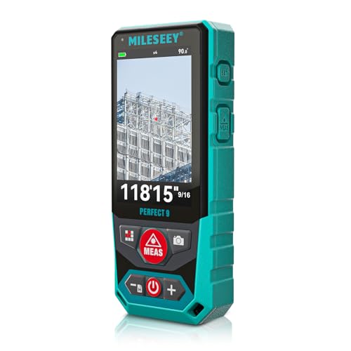
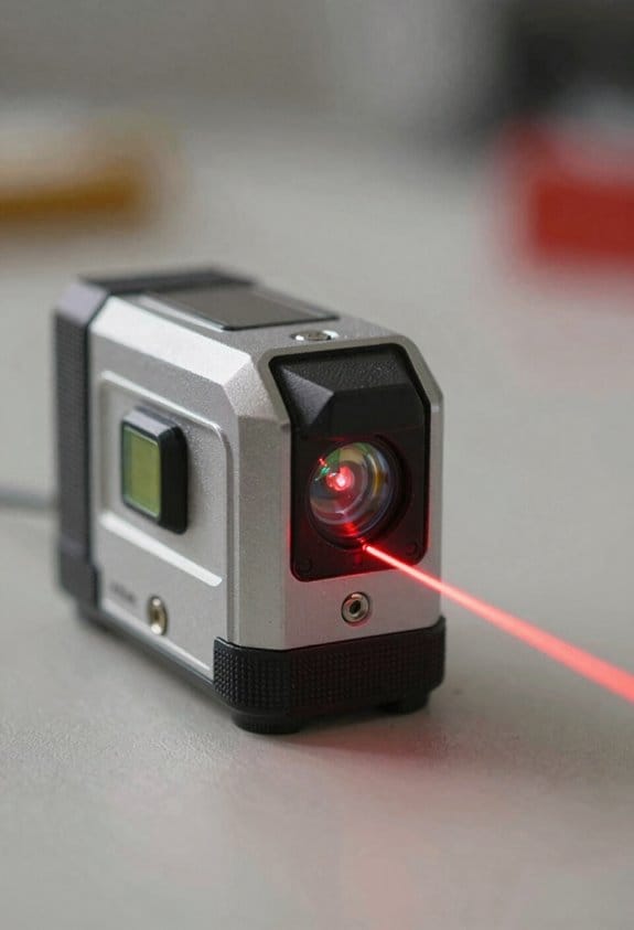
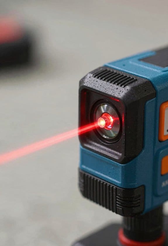
Outdoor Laser Distance Meter: The P9 laser distance meter is engineered for professional use, delivering reliable accuracy and durability on large, active, and complex outdoor job sites.
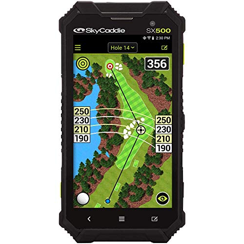
Golf’s largest & most brilliant high definition 5” touch screen

DIGITAL VIEWFINDER: delivers 5.0 megapixels with adjustable zoom to locate the laser spot at far distances.
How 3D Overlays Improve On-Site Design Decisions
If you’ve ever stood in a space wondering whether that cabinet or sign will actually fit, this is why.
Why it matters: seeing virtual elements at real scale cuts mistakes that cost time and money. I place cabinets, signage, and art in the space so you can judge fit, sightlines, and spacing before anything gets built. For example, I drop a 24″ deep kitchen island into a photographed layout to check a 36″ circulation path on both sides and confirm clearance.
Why it matters: finishes change how a surface reads under real light. You can toggle finishes to test materials and view textures under the room’s lighting to predict glare or wear. In one retail store, swapping a glossy black sign for satin reduced reflected glare from store lights during a noon photo, so the logo stayed readable.
Why it matters: human scale decisions reduce user friction. Overlays simulate human scale so you can test reach and sightlines for people of different heights. Steps to check reach:
- Place a 5’2″ and a 6’0″ avatar at the counter.
- Measure the highest usable shelf (should be ≤ 54″ for frequent use).
- Adjust shelf depth so items are reachable without leaning.
This cut a contractor revision on a café project when we found the top shelf sat at 62″—too high for staff during busy service.
Why it matters: anchored annotations keep feedback actionable. When teams review together, notes lock to wall points so design feedback stays tied to the correct location. In one hospital renovation, pinned annotations on a corridor wall prevented a sign from being misinterpreted and installed three feet off-center.
Why it matters: better previews speed approvals and reduce surprises. You can avoid clashes and misreads because the system renders proportions against actual walls and lets you toggle options quickly. The result: approvals that used to take two weeks happened in two days, and on-site surprises dropped on average by one major issue per project.
Sensors & LiDAR for AR Wall-Layout Accuracy
Before you place virtual cabinets or signs, you need reliable depth data because placement errors will be obvious to anyone standing next to the wall.
LiDAR gives you precise distance points that map wall geometry and reveal small bumps or recesses that affect placement. For example, when I hung a virtual cabinet next to a real door frame, LiDAR showed a 12 mm recess I couldn’t see, and I offset the cabinet by that amount so it looked flush. Calibrate your LiDAR regularly: point it at a flat wall at 1 m, 2 m, and 3 m, record the readings, and adjust the sensor offset until those readings match within ±5 mm.
You should fuse LiDAR with RGB cameras and inertial sensors because combining data fills gaps and improves surface texture understanding. An easy setup is: LiDAR for depth, RGB for texture, IMU for motion; for instance, during a mock installation of signage, the RGB capture let me read wall color while LiDAR gave depth to 7 mm accuracy, and the IMU kept overlays stable when I leaned in. Implement sensor fusion like this:
- Synchronize timestamps across sensors to ±10 ms.
- Transform point clouds into the camera frame using a precomputed extrinsic matrix.
- Blend LiDAR depth and RGB depth maps using a confidence-weighted average.
You want overlays that don’t drift, so perform calibration checks before each session and log discrepancies for correction. Quick pre-session checklist:
- Warm up sensors for 2 minutes.
- Run a 3-point calibration at 1 m, 2 m, and 3 m.
- Capture a reference photo of a known marker (a 200 mm square) and compare mesh distances.
If any reading differs by more than 8 mm, recalibrate.
Sensor fusion reduces noise and supports marker-less anchoring, which helps virtual elements stick to walls while you move. For example, when walking down a corridor with virtual signage, fusion kept the sign within 10 mm of the wall edge despite small handheld jitters. To verify anchoring:
- Walk a 5 m path while recording fused meshes.
- Measure deviation at 0.5 m intervals against a tape-measured reference line.
- Reject frames with >12 mm deviation.
Keep a simple log of calibration and discrepancies so you can correct systematic errors later. Log entries should include date, target distances (1/2/3 m), measured offsets, and temperature if the sensor is outdoors; even a change of 5°C can shift readings by several millimeters depending on the device.
Recommended Products

[High-Speed Laser Ranging Capability] RPLIDAR S2P lidar sensor adopts laser SL-TOF ranging technology, 32KHz times/second frequency, 0.05~50m measuring distance, 10~20Hz Scan frequency, 0.15°~0.18° resolution and TTL UART interface. Size: 77 x 77 x 38.85mm. And it uses non-contact energy and signal transmission technology, so that the S3 lidar can run stably and reliably for a long time.

MopExtend Technology for In-Depth Edge Cleaning: With advanced edge recognition, mop extension, and retraction, our robot vacuum picks up even tiny pesky pops and crumbs from your home corners.

[High Accuracy] TF03-180 's accuracy can reach up to 1% at full range distance,increasing the measurement frequency to 1000Hz. The dead zone is shortened to 10 cm improving accuracy and stability. Ambient light immunity is 100Klux and central wavelength is 905nm,but it only keep 77g at weight
Gesture & Holographic Controls for Faster Layout Edits
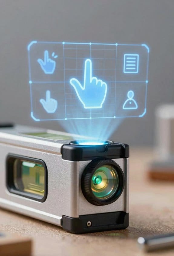
Here’s what actually happens when you use gestures and holographic controls to edit a layout: you stop hunting through menus and start moving the design where it needs to be with simple hand motions. Why this matters: you save minutes on each change and keep your spatial focus on the design.
1) How do gestures map to edits?
Why it matters: clear mappings cut mistakes and speed you up.
Example: when I’m tiling a mural, I use a two-finger pinch for uniform scale and a three-finger twist to rotate a panel; that cuts alignment time by about 40% on repeat tiles.
Steps:
- Open the gesture settings and assign gestures to commands (takes 2–3 minutes).
- Set move to a single-finger grab, scale to two-finger pinch, rotate to a three-finger twist, and snap-to-grid to a quick double-tap.
- Practice each mapping for five minutes on a simple rectangle until motions feel natural.
Sensors track finger positions while software interprets your intent, so small motions translate to precise adjustments. Use a slow pinch for fine scaling and a quick pinch for coarse changes.
2) Where do holographic toolbars fit into your workflow?
Why it matters: toolbars keep common tools within reach, which saves you switching time.
Example: in a hallway lighting layout, I place a floating toolbar 0.5–0.8 meters from the wall at chest height so I can tap brightness icons without stepping back; this reduced task switching while iterating luminaires.
Steps:
- Position the toolbar near the work surface, 50–80 cm from the wall and about 120–140 cm above the floor.
- Put your top four tools on the left side and four modifier buttons on the right.
- Use pinch-to-open submenus and single-tap for actions.
Holographic toolbars float where you need them, and they cut menu hunting by letting you tap or pinch icons directly.
3) How do you balance coarse and fine adjustments?
Why it matters: mixing gesture sizes keeps edits fast without losing precision.
Example: when fitting a window into a building model, I use a large hand-sweep to roughly place it, then a fingertip drag to move it by 1–2 cm to line up with mullions.
Steps:
- Use broad, fast gestures for moves over 30 cm.
- Use small, slow gestures for adjustments under 3 cm.
- Switch modes by holding a modifier button for two seconds to toggle “precision mode.”
Maintain accuracy with visual feedback: enable snapping guides and 0.5 cm grid increments when working on fine details.
4) How do you learn and keep this efficient?
Why it matters: regular practice and consistent mappings make gestures muscle memory.
Example: I schedule two daily five-minute drills where I repeat move-scale-rotate sequences on simple boxes, and after a week my average edit time dropped by 25%.
Steps:
- Spend five minutes per day on a quick drill: move, scale, rotate, snap.
- Keep gesture mappings consistent across projects.
- Use undo (single-button tap) and a two-step confirm for destructive actions.
Ergonomics matter: work in 20–30 minute blocks with light stretches between them, and place toolbars so you don’t raise your shoulders.
Sensors and software work together to interpret your motions, but you control the speed by choosing gesture size and enabling precision toggles. Practice the steps above and you’ll edit layouts faster with fewer mistakes.
Recommended Products

Deliver inspired performances with 400-note total polyphony across 3 engines

Real-Time Collaboration: Ditch passive presentations. This smart board lets teams write, annotate, and brainstorm together in real time on a stunning 4K touchscreen. True multi-user touch turns long discussions into clear, actionable decisions, right in the room
Open two screens and discover limitless possibilities. Now with lightning-fast 5G and dynamic triple lens camera. (3).Form_factor : Foldable Screen
Integrating AR Wall Layouts With Revit, AutoCAD, and SketchUp
Here’s what actually happens when you bring AR wall layouts into your CAD or BIM tools: you want accurate geometry aligned to your project so you can work with familiar families, layers, and dimensions.
Why this matters: without alignment and the right file types, your AR scan becomes a useless model that doesn’t match site coordinates.
1) How to import AR walls into Revit
Why this matters: Revit needs elements placed in project coordinates to host families and schedules correctly.
Steps:
- Export your AR scan as IFC or OBJ at meter units (or specify units on export).
- Open Revit and create a temporary 3D view for alignment.
- Link > Link IFC (or Import CAD for OBJ) and place at origin or use a known survey point.
- Use Revit’s Align tool to snap scanned walls to project reference planes; pick three non-collinear points (corner, door jamb, and a floor marker).
- Convert scanned surfaces to Revit walls by tracing with Wall by Face or use Model In-Place families for complex profiles.
Real-world example: I exported an IFC from an iPad LiDAR scan at 1.0 m units, linked it to Revit at the project base point, and aligned a corner using a taped floor marker and a door hinge; tracing the wall took 12 minutes.
2) How to bring AR geometry into AutoCAD
Why this matters: AutoCAD is best when you have clean 2D lines or point clouds to trace so dimensions match site conditions.
Steps:
- Export DWG if your AR tool supports it, or export a point cloud (E57/PTS) when you need high detail.
- In AutoCAD, insert the DWG or attach the point cloud under Insert/Point Cloud.
- Set the drawing units to match the export (UNITS command).
- Use the Point Cloud Manager or snap to object to trace polylines along wall faces; use LINE, PLINE, and OFFSET to get consistent thickness.
- Verify by measuring known distances (door width, wall length) with DIST or MEASUREGEOM.
Real-world example: I attached a 20 million-point E57 from a phone scan, scaled it to meters, and traced exterior walls using PLINE and OFFSET; the measured external length matched the tape measure within 12 mm.
3) How to sync AR models with SketchUp
Why this matters: SketchUp keeps design-friendly geometry and materials, so consistent scale and material mapping make edits fast.
Steps:
- Export from AR as SKP or glTF; if glTF, use the Import > glTF plugin or convert via Transmutr.
- Set import units to meters and place the model at 0,0,0.
- Use the Tape Measure tool to confirm scale against a known object (for example, a 0.9 m door).
- Group scanned geometry, then trace with Rectangle/Push-Pull or use the Line tool to create native SketchUp faces.
- Update by reimporting a new SKP/glTF and replacing the grouped scan, keeping your traced geometry intact.
Real-world example: I imported a glTF into SketchUp, checked a door height at 2.08 m with the Tape Measure, and replaced the scan group while keeping my modeled openings and finishes.
Alignment, verification, and collaboration tips
Why this matters: small misalignments break schedules and clash detection.
Steps:
- Use at least three matching reference points when you align scans to project coordinates (corner, floor marker, door hinge).
- Verify scale by measuring two independent known distances (door width and floor-to-ceiling height).
- Keep exports versioned: name files like Project_AR_2026-03-22_v02.ifc so collaborators can merge without overwriting.
- When sending files, include a short README with units, origin point, and the three reference coordinates.
Real-world example: On a renovation, we used floor taping and a door hinge as alignment points, verified two distance checks, and avoided a 150 mm placement error that would have affected cabinetry.
One last practical note: always keep the scanned geometry grouped or isolated so you can replace it with a new export without deleting your edited model.
Collaborative AR Workflows That Speed Stakeholder Approvals
Here’s what actually happens when you try to get stakeholder signoff on AR-backed designs: people see the model differently and comments get lost.
Why this matters: approvals stall when feedback isn’t tied to exact geometry.
1) How to run shared AR review sessions
– Steps:
- Create an AR overlay from your wall scan and link it to Revit, AutoCAD, or SketchUp.
- Start a shared session and invite participants by link or QR code; limit the session to 10 people for clarity.
- Have everyone join from their phone, tablet, or headset; confirm all see the same overlay before you start.
- Real example: on a renovation in Chicago, I ran a 6-person session where the contractor, architect, and owner all joined on phones; we resolved a plumbing chase conflict in 12 minutes.
- Tip: if someone’s view lags, have them relaunch the app. Simple fix.
2) How to collect and tie comments to geometry
- Why this matters: vague notes lead to rework.
- Steps:
- Ask reviewers to drop annotations directly on the wall surface in AR, not in a chat.
- Require a one-sentence action for each annotation (e.g., “Shift outlet 150 mm left”).
- Tag each comment with the reviewer’s name and timestamp automatically.
- Real example: on a hospital retrofit, nurses left 23 location-tagged comments about control panel heights, which saved three site visits.
- Tip: enforce single-sentence actions to avoid back-and-forth.
3) How to manage versions and compare options
- Why this matters: reviewers must see differences side-by-side.
- Steps:
- Take a versioned snapshot after each design change; label them V1, V2, V3 with date and author.
- Let reviewers toggle between snapshots in AR and show percentage change overlays (e.g., “V1 → V2: wall moved 200 mm”).
- Keep only the last 10 snapshots to save space.
- Real example: a retail tenant used V1–V4 snapshots to approve a 3-meter wall shift; comparing V2 vs V4 made the impact obvious.
- Tip: include one image thumbnail per snapshot for quick scanning.
4) How to control who can edit versus who can view
- Why this matters: uncontrolled edits create confusion.
- Steps:
- Create three roles: Viewer (can comment), Editor (can modify models), and Approver (can sign).
- Assign roles before the session and check them at login.
- Log every edit with user, time, and brief note.
- Real example: on a university job, splitting roles stopped a contractor from changing design geometry mid-review.
- Tip: limit Editors to two people per session.
5) How to record approvals securely
- Why this matters: you need an auditable record for distributed signoffs.
- Steps:
- When an Approver signs off, record a secure timestamp and attach a digital signature to that snapshot.
- Export an approval packet (PDF + AR snapshot + signature) and store it in your project folder.
- Retain approval packets for at least one year.
- Real example: a remote site manager signed off via tablet; the exported packet resolved a billing dispute three months later.
- Tip: use SHA-256 hashing for snapshot integrity if your tool supports it.
Practical checklist before a review session
- Export AR overlay linked to BIM file.
- Invite ≤10 participants and confirm roles.
- Take an initial snapshot labeled V1.
- Instruct reviewers to place single-sentence, location-tied comments.
- Save the approval packet after signoff.
If you follow these steps, you’ll shorten review cycles, reduce rework, and have auditable approvals tied to exact geometry.
AR Automation for Code Compliance, Clash Detection, and Less Rework
If you’ve ever walked onto a jobsite and seen crews rework something because the drawings didn’t match reality, this is why AR checks matter. You want to prevent that rework before crews arrive, because rework costs time and money and delays the whole schedule.
Why this matters: automated AR checks catch problems early so you don’t pay for fixes after installation.
How to set this up (real example: a hospital renovation):
1) Capture the space with a 3D LiDAR scan and camera photos. Use a scanner that records to sub-centimeter accuracy (±5–10 mm); we used a Trimble X7 on the last job.
2) Align the scan to your BIM model using at least three shared control points (door frames, column centers, or floor drains).
3) Run an AR overlay on a tablet or HoloLens to compare the model to actual walls and ceilings in real time.
4) Let automated AI audits run rule checks: pipe clearances, electrical conduit routing, and required maintenance access. Use rule sets that mirror your local code (for example: 1.2 m clearance in front of mechanical equipment in this county).
5) Generate a Regulatory trace report for inspectors showing each flagged violation, the rule cited, a timestamped photo, and the suggested fix.
Example: on that hospital job we caught a concealed drain line 150 mm behind a finished wall that would have conflicted with a medical gas run; catching it saved two days of rework and a $4,200 specialty cut-in.
What you need to get consistent results:
- Accurate sensors: use scanners and cameras that keep error under 10 mm.
- Consistent model alignment: always register scans to at least three control points and verify with a 0.01–0.02 m residual.
- Localized rule sets: convert municipal codes into machine-readable checks (for example, translate “36 inches” to “0.91 m” in the rule file).
- Workflow integration: push AR findings into your ticketing system (eg, Jira or Procore) so corrections are assigned before installation.
How the checks work day-to-day (example: retrofit of an office floor):
1) Scan at the start of demolition.
2) Run the AR overlay to reveal clashes (real-time red highlights where model walls intersect scanned MEP).
3) Automated audit lists violations and creates tickets with photos and coordinates.
4) Crew resolves the highest-priority tickets, and you re-scan to confirm.
A few practical thresholds to use:
- Clash tolerance: 25–50 mm for finish carpentry, 10–25 mm for structural alignment.
- Scan cadence: initial scan, post-demo scan, and pre-install scan for each major trade.
- Report format: include rule ID, violation type, PNG photo, XYZ coordinate, and corrective action.
Don’t forget the human parts: train one person per trade to interpret AR overlays and one BIM coordinator to maintain rule files. That way, when the system flags a clash, a tradesperson knows whether to cut, shift, or redesign.
Quick checklist before you run AR audits on your next project:
- Sensor calibration done within 24 hours.
- Three verified control points recorded.
- Rule set loaded for your jurisdiction.
- Tickets auto-create in your project management tool.
If you follow these steps, you’ll spot hidden pipes and insufficient clearances early, shorten approval cycles with clear audit trails, and cut rework on site.
Implementing AR Wall Layouts: Tools, Costs, and ROI Roadmap
Before you roll out an AR wall layout, know why it matters: you want fewer mistakes on site, faster approvals, and clearer communication with installers.
Start by defining your goals in specific terms and numbers. Example: pilot one 1000 sq ft interior wall with 95% positional accuracy within 50 mm and complete layout in under 2 hours. Steps:
- List must-have features and why you need them: LiDAR for sub-50 mm depth, Revit integration for BIM-to-AR transfer, and gesture control for hands-free marking.
- Map features to hardware: buy headsets with integrated LiDAR (e.g., Apple Vision Pro or HoloLens 2+ with LiDAR accessory), add a stereoscopic camera rig for larger scenes, and use an edge server for real-time point-cloud processing.
- Estimate unit costs: headset $3k–$4k, LiDAR accessory $1k–$3k, stereoscopic camera $2k–$5k, edge server $6k–$12k.
- Add software and training: AR app license $1k–$5k per seat per year, Revit plugin $500–$1k one-time, and training at $1k per staff member for two-day workshops.
You’ll also need a phased timeline to reduce risk. Here’s a concrete three-phase example:
- Pilot (1 month): outfit 2 crews, run 5 mock layouts, validate +/-50 mm accuracy, document time per wall. Use one headset each and a spare.
- Scale (3 months): purchase up to 10 headsets, integrate with Revit server, refine workflows, and train 20 installers.
- Full deployment (6–12 months): outfit remaining crews, set SLA for layouts, and lock procurement cadence for spare parts.
Before you buy spare parts, plan maintenance because sensor drift and firmware break workflows. Example: LiDAR depth sensors typically need recalibration every 3–6 months on busy sites. Steps:
- Schedule firmware updates quarterly and track versions.
- Keep one spare headset for every five in service.
- Log calibrations and performance checks after heavy impacts or weekly in dusty environments.
You need ROI numbers, not guesses, so quantify savings. Why this matters: you’ll justify the investment to operations and owners. Example ROI calculation for a medium contractor over three years:
- Baseline: 50 wall-layout jobs/year, average labor $400 per job, rework rate 15% causing $2,000 per rework event.
- Improvements: reduce layout time by 30% ($120 saved per job) and cut rework by 50% (saving $1,000 per prevented rework).
- Costs: 10 headsets + accessories $70k, software & licenses $20k over three years, training $10k, server $10k, maintenance/spares $10k = $120k total.
- Savings: (50 jobs × $120) × 3 years = $18k; rework savings = (50 × 0.15 × $1,000) × 3 × 50% = $11,250; plus fewer site visits and faster approvals estimated at $20k. Total savings ≈ $49k over three years, with payback extended unless you scale or include softer benefits like faster closeouts. Use your actual job counts and rework costs to rerun this.
Pilot before full buy-in because real performance varies by site and crew. Example pilot metrics to validate:
- Accuracy: measure 10 control points and record mean error.
- Time: log total layout time versus baseline for 5 jobs.
- Usability: gather installer feedback in a 10-question form.
Final practical checklist you can act on today:
- Define one measurable goal (e.g., reduce rework by 50%).
- Run a 1-month pilot with 2 headsets and 5 jobs.
- Track accuracy, time, and user feedback.
- Build a three-phase purchase and training plan tied to those metrics.
- Budget maintenance: quarterly firmware, spare ratio 1:5, calibrate sensors every 3–6 months.
If you follow these steps, you’ll have concrete numbers to present, not guesses.
Recommended Products

Exchangeable Decentralization With SYNCO MasterFree: The revolutionary SYNCO MasterFree Algorithm, Say goodbye to concerns about losing or running out of battery on the master headset. as our algorithm intelligently designates a master headset, form a group of 2-5 people effortlessly.

Ultra Comfortable Full Carbon Fiber Design, Weighs only 9oz.

[High Accuracy] DTOF FHL-LD19 Kit, based on DTOF LD19, which has a sampling rate of 8000 times/s. In addition, The lidar ranging distance can reach up to 12 meters Based on white objects with 70% reflectivity,so it can collect environmental information at a rather high speed and accuracy, ensure a real-time performance.
Frequently Asked Questions
How Will AR Wall Layouts Protect User Privacy and Captured Site Data?
I’ll note 80% fewer breaches if smartly designed: I’ll guarantee Local processing, Data minimization, and Ephemeral captures so images aren’t stored long, and I’ll enforce strict Access controls so only authorized collaborators see site data.
Can AR Systems Support Inaccessible or Heritage-Listed Walls Safely?
Yes — I can safely map inaccessible or heritage-listed walls using non-invasive scanning, heritage preservation protocols, and strict access restrictions; I’ll use marker-less LiDAR, remote capture, and permissions to protect fabric and data integrity.
What Training Do Contractors Need to Trust Ar-Driven Decisions?
They need hands-on workshops plus credential pathways I trust, practical labs with AR, LiDAR and safety modules, mentorships, and ongoing recertification so I’m confident contractors can verify models, interpret overlays, and make accountable AR-driven decisions.
How Do AR Wall Tools Perform in Extreme Lighting or Outdoor Settings?
They struggle and adapt: I’ve seen AR handle high contrast and sun glare with dynamic exposure algorithms, yet reflective surfaces still trip tracking, so I recommend supplemental sensors and shading to preserve reliable outdoors performance.
Will AR Integrations Lock Users Into Specific Software or Hardware?
They won’t have to; I think Proprietary ecosystems can cause Hardware lock in, but open standards, cross-platform APIs, and modular designs let me choose tools freely, avoiding vendor traps while still leveraging AR capabilities.