You’ve just tried to solder a tiny MCU pin and ended up with a blob bridging three pads, or your 3D printed hinge won’t fit despite matching the CAD.
The exact problem is inconsistent small-scale control — heat, static, and careless material removal ruining tolerances and fit. Most people blame the parts or settings instead of the tools and technique that control micro-scale work.
This piece will show you which compact precision tools to use, how to use them to make repeatable fits and clean solder joints, and how to measure and log tolerances so parts mate reliably.
You’ll also get simple habits for preserving dimensions on prints and preventing thermal or ESD damage.
It’s easier than it looks.
Key Takeaways
If you’ve ever tried fixing tiny joints or fitting 3D parts, this is why.
Why it matters: precise heat control prevents damage to small components so your board actually works afterward. For example, when repairing a phone’s charging port, use a soldering iron that can hold 300–350°C steady so the nearby connectors don’t lift.
1) Use compact precision soldering and hot-air tools
- How: set your iron to 300–350°C for leaded solder and 350–400°C for lead-free; use a 0.5–1.0 mm conical or bevel tip; keep hot-air at 250–300°C for tiny surface-mount rework and use a 2–4 mm nozzle.
- Real-world example: reflowing a 0603 resistor with a 0.8 mm tip and 280°C for 2–3 seconds avoids heating the IC beside it.
If you’ve ever tried to hold a PCB steady while you work, this is why.
Why it matters: stable parts let you make the same precise move every time, so joints look clean and parts align correctly. For instance, stabilizing a 3D-printed hinge during gluing prevents misalignment when the adhesive sets.
2) Use small fixturing and third-hand clamps
- How: clamp the PCB at two points with foam pads, or use a V-block for cylindrical parts; set clamp pressure just enough to stop movement but not crush the board.
- Steps:
- Place part in jig.
- Add foam or soft pads where the clamp contacts.
- Tighten until snug, then test movement.
– Real-world example: holding a 50 × 40 mm PCB with a third-hand and a small vise makes soldering through-holes faster and cleaner.
Think of magnification like a magnifying glass for errors.
Why it matters: seeing the defect lets you fix it precisely so you don’t rework the same spot repeatedly. While inspecting a 3D print, 10–20x magnification shows layer bonding flaws and 30–45x reveals tiny surface bubbles.
3) Use magnification and adjustable LED lighting
- How: choose a loupe or binocular microscope with 5–45x range and daylight-balanced LEDs (5,500–6,500 K); position light at a 30–45° angle to avoid glare.
- Real-world example: using 20x magnification and a 6,000 K ring light reveals whether a solder fillet has flowed correctly around a pad.
If you’ve ever fried a chip with static, this is why.
Why it matters: ESD events can kill sensitive parts instantly even if they look fine afterward. For example, handling an exposed MOSFET without grounding can render it nonfunctional despite a perfect-looking solder.
4) Use ESD-safe tweezers, mats, and wrist straps
- How: pick tools labeled ANSI/ESD S20.20 or IEC 61340 compliant; connect the wrist strap to a common ground and verify continuity with a meter (100 kΩ nominal to ground).
- Real-world example: using ESD-safe tweezers to place an SOT-23 transistor prevents unseen damage when you touch the board.
Before you remove material, you need to control how much you take off.
Why it matters: removing too much plastic or filament ruins fit and weakens parts; removing too little means poor mating and stress. When trimming a dovetail on a 3D-printed connector, consistent 0.2–0.5 mm passes give repeatable fits.
5) Use small, controlled material-removal tools and simple jigs
- How: use a hobby rotary tool at 10,000–20,000 RPM with 1–2 mm burrs for light trimming; clamp parts in a simple guide that keeps pressure even and depth limited to 0.2–0.5 mm per pass.
- Steps:
- Mark the cut line.
- Secure the part in the jig.
- Remove material in measured passes, then test fit.
– Real-world example: trimming a 3D-printed peg in 0.3 mm increments until it slides into the socket prevents cracking and ensures a snug fit.
Compact Precision Tools for Electronics Assembly and Repair
Before you start soldering, you need to know why precision tools matter: they let you work on tiny parts without overheating or dropping them.
You use a fine-tip soldering iron (15–30 W with a 0.5–1.0 mm tip) for micro joints because it heats small pads quickly and cools fast, which reduces thermal stress. Example: when soldering an SMD resistor on a crowded board, you heat the pad for 1–2 seconds, apply solder, then remove heat—this avoids lifting the pad. Steps:
- Set iron to 300–330 °C for leaded solder or 340–370 °C for lead-free.
- Tin the tip with a small amount of solder before touching the joint.
- Heat the pad and component lead together for 1–2 seconds, feed solder, then remove the iron.
Use magnification (5–10x loupe or microscope) to inspect the fillet and confirm a shiny, concave joint.
If you’ve ever lost a chip to static, this is why ESD control matters: a tiny spark can instantly ruin a component even if it looks fine afterward.
Keep your parts in anti-static bags or bins and use an ESD-safe mat and wrist strap. Example: when replacing a Wi‑Fi module, lay the board on a grounded mat, clip your wrist strap to the mat, and keep the module in an ESD bag until you’re ready. Steps:
- Connect wrist strap to earth ground or to the mat’s ground point.
- Test wrist strap/mat continuity weekly with an ESD tester.
- Store sensitive ICs in foam-topped conductive boxes when idle.
Think of steady hands like a camera tripod for your fingers; stabilization prevents accidents and improves accuracy.
Use precision tweezers (ESD-safe, fine-point), micro screwdrivers (PH000, T2), and flush cutters to position parts and trim leads. Example: when removing solder bridges between two pins on an IC, use tweezers to lift the component slightly while you wick with solder braid. Steps:
- Secure the board with a PCB holder or third-hand tool.
- Use tweezers to hold the component or lift a pad edge.
- Apply solder wick and the iron for 1–3 seconds to remove excess solder.
- Trim leads with cutters and deburr if needed.
Before you rework a joint, you need to know how to avoid heat damage.
Use short contact times and targeted heat: preheat the board to about 50–80 °C for larger boards to reduce thermal shock, and always use flux to improve wetting so you need less heat. Example: reflowing a tiny capacitor, apply a dab of flux, heat for 1–2 seconds with a hot air gun at 260 °C (small nozzle, 2–3 cm away), then let it cool on the mat. Steps:
- Apply flux to the joint.
- Heat for the minimum time needed to flow solder (1–3 seconds for hand soldering).
- Remove heat and allow the part to cool on the ESD mat.
If you want consistent results, you need to calibrate and maintain your tools.
Check iron tip condition weekly, replace tips after obvious wear, and recalibrate temperature every 3–6 months with a thermocouple or a reference board. Example: when your solder joints start looking grainy, test the iron tip temperature with a thermocouple and clean or replace the tip. Steps:
- Clean the tip on a brass sponge, then tin it.
- Verify temperature with a thermocouple or tip tester.
- Replace the tip if it’s pitted or won’t hold solder.
When you follow these steps, you’ll reduce component failure, avoid lifted pads, and finish jobs faster with fewer retries.
Recommended Products
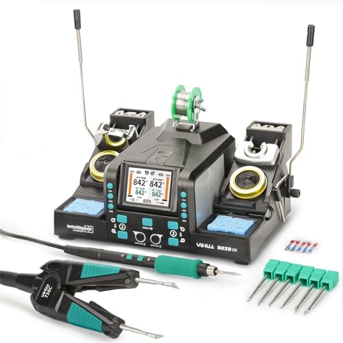
Dual-Handpiece Soldering Iron Kit: Use C120 hot tweezers and C210 soldering iron simultaneously; ideal for multi-tasking on precision soldering projects and hot tweezers soldering and saving the hassle of swapping tools

Adjustable temperature range of 200-500°C (392-932°F)
Safe - the soldering iron uses industry leading Weller closed-loop method of controlling maximum tip temperature to protect yourself and your workstation from over temperature and is ul and cul listed
Key Compact Precision Tools for Microelectronics
Here’s what actually happens when you work on tiny circuit boards: you need the right compact precision tools so you don’t burn, lose, or break parts.
Why it matters: using the wrong tool ruins components and wastes time. Example: when I tried removing an SOT-23 regulator with a regular soldering iron, the pads lifted in seconds; a micro iron with 1.2–1.5 mm tips saved the board.
1) Which soldering iron should you get?
Why it matters: controlled heat stops pad lift and component damage. Example: reattaching a 0603 resistor with a 15–25 W micro iron and a 1.2 mm chisel tip, I soldered it in under 10 seconds without heat damage.
Steps:
- Choose a temperature-controlled iron settable to 200–350 °C.
- Pick tips around 0.6–1.5 mm for SMT work.
- Use flux and a 0.3–0.6 mm solder wire (Sn63Pb37 or SAC305) for small pads.
End detail: set idle temp lower, then heat to working temp only when soldering.
2) Do you need ESD-safe tweezers?
Why it matters: static kills chips instantly. Example: placing a QFN with metal tweezers once discharged the part; ESD-safe nano tweezers saved the next one.
Steps:
- Buy ESD-safe stainless tweezers with tips under 0.3 mm spacing.
- Verify they’re dissipative (10^6–10^9 ohms) with an ohm meter.
- Use a grounded wrist strap when handling naked ICs.
End detail: hold chips by the body, not by the leads.
3) Which magnification helps you see solder joints?
Why it matters: you can’t fix what you can’t see. Example: inspecting a BGA under 10x stereo microscope revealed a single bridged ball I missed under a lamp.
Steps:
- Get either a 3–45x stereo microscope or a 5–10x magnifying inspection lamp.
- Aim for LED lighting with adjustable brightness and color temperature.
- Use a camera adapter if you need to document work.
End detail: start at low magnification to orient, then increase to check solder fillets.
4) What cutters and pliers work best?
Why it matters: clean cuts prevent shorts and strain. Example: trimming component leads flush with flush-cut cutters prevented a stray lead touching an adjacent trace on a packed dev board.
Steps:
- Use flush-cut cutters rated for electronics and hardened to stay sharp.
- Use flattened-tip or needle-nose pliers for bending and holding leads.
- Trim leads 0.5–1.0 mm from the pad for through-hole parts.
End detail: cut perpendicular to the lead to avoid crushing.
5) When should you use hot air rework?
Why it matters: hot air removes parts without dragging solder across pads. Example: removing a 16-pin SOIC with preheater and a 2–3 mm nozzle at 300–350 °C let the package lift cleanly.
Steps:
- Preheat the board to 80–120 °C if possible.
- Use a temperature-controlled station and start at 250–300 °C; increase in 10 °C increments if needed.
- Use a nozzle sized to the package (e.g., 2–3 mm for SOIC, 8–12 mm for QFP).
- Keep airflow low—around 10–20 L/min—to avoid tossing tiny parts.
End detail: cool the board gradually and use solder wick to clean pads after removal.
Final tip: keep a small kit with a 15–25 W micro iron, ESD tweezers, 5–10x magnifier, flush cutters, flattened pliers, and a hot air station; that combo handles most microelectronics tasks reliably.
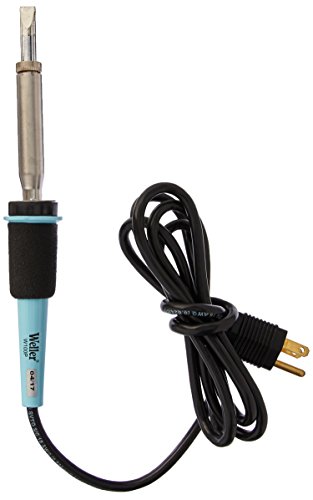
Recommended Products

The new Pico (Nano)/Micro Soldering tool has the fastest heat-up and recovery times of less than 3 seconds. Excellent heat transfer and recovery time during the soldering process for a high performance and continuous workflow. The short tip-to-grip distance provides maximum precision during the soldering process.

Technical Parameter: Power supply: AC110 V/ (50~60) Hz, rated power: 2900 W, drawer panel area: 23.6x15.7 Inch (600x400 mm), temperature range: 0℃-280℃, cycle time: 1~9 min, rated duty cycle: 100%

The Hakko FX-972 Dual Port Soldering Station is a 200W soldering station that has the power to utilize multiple handpieces for various operator needs
Post-Processing 3D Prints With Precision Tools for Better Fit
Before you do final fit-up, know why precision matters: small high spots or layer lines can stop parts from seating and cause stress or misalignment.
Here’s what actually happens when you remove layer lines for seating: the part goes from binding to sliding into place, and the assembly behaves like the CAD model. Example: a 3D-printed hinge that won’t close because a 0.2 mm ridge on the pin hole locks it at 10 degrees; remove 0.15 mm and it closes fully. Use these concrete steps:
- Clamp the part in a simple jig or vise with soft jaws so it doesn’t shift.
- Start with a 400–600 grit needle file or a micro-sander at low speed.
- Remove 0.1–0.2 mm per pass where interference occurs.
- Check the fit after each pass against the mating part.
Finish with 800–1200 grit for a smooth contact surface.
If you’ve ever tried to clear tight mating features and gone too far, you’ll want controlled gap adjustment because overcutting ruins the part and wastes time.
Why this matters: stopping early saves you from reprinting the piece. Example: a press-fit boss that needs 0.5 mm diameter reduction — if you remove 0.8 mm you’ll get loose, unusable parts. Follow these steps:
- Mark high spots with a pencil or transfer film while the parts are assembled.
- Use needle files or soft abrasive sticks to remove the marks in tiny increments.
- Reassemble and test after every 30–60 seconds of work.
- When the fit is snug but removable, measure and record the final dimensions.
You don’t need expensive equipment if you’re careful about tool choice because small, targeted tools give more control than big rotary bits.
Why this matters: the wrong cutter takes material too fast and overheats the plastic. Example: clearing a slot for a circuit board — using a 1.5 mm carbide cutter at 10,000 RPM will melt PLA; using a 2.5 mm sanding drum at 5,000 RPM removes material cleanly. Use this order:
- Start with soft abrasive sticks or fine needle files for delicate features.
- Switch to small carbide cutters (1–3 mm) for harder areas, keeping RPM under 10k.
- Use short bursts and cool with compressed air or pauses to avoid melting.
- Finish with a 400–1200 grit hand-sanding pass.
Think of holding the part like steadying a scalpel during surgery: consistent angle and pressure give predictable results.
Why this matters: inconsistent pressure leaves uneven surfaces and unpredictable fits. Example: sanding a flat mating face freehand can create a bow; using a flat-backed jig keeps the face true. Steps to set up:
- Make a simple fixture from scrap acrylic or plywood sized to the part.
- Secure the part with double-sided tape or soft clamps.
- Use the same stroke angle and count for each pass.
- Verify flatness with a straight edge or feeler gauge.
Finish with a fine grit and re-test the assembly because small surface differences change contact behavior.
Why this matters: a smoother surface spreads load and reduces wear. Example: a bearing surface polished to 1200 grit lasted twice as long in a test mount than the same surface left at 400 grit. Steps:
- Work up grit sizes progressively: 400 → 800 → 1200.
- Rinse or blow off debris between grits.
- Re-check fit and function after the final grit.
Recommended Products

Rich in Natural Nutrients: Step into a world where every serving is a treasure chest of antioxidants sourced directly from nature. Our Rutin powder, in Rutin 500mg, harness the earth's bounty, providing you with the essential nutrients required for a flourishing overall health and well-being.
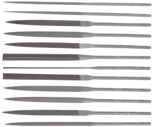
Set of 12 files in a variety of shapes for a range of precision uses

DURABLE STORAGE BOX – Includes a sturdy, protective plastic case that keeps the diamond needle files safe from damage—perfect for storing in a tool trolley, toolbox, or workbench drawer.
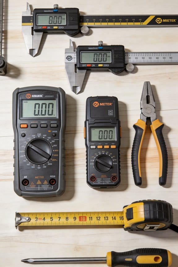
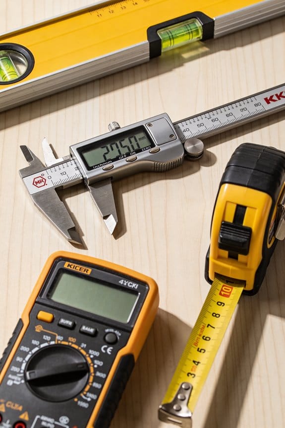
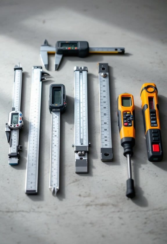
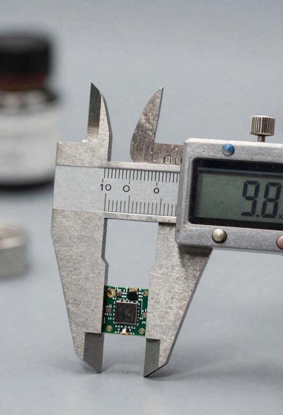
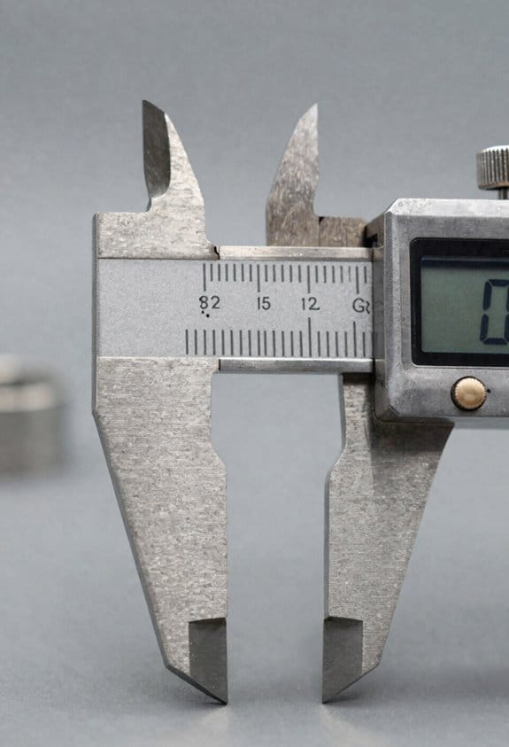
Measurement: Micrometers, Calipers, CMMs, and In-Line Sensors
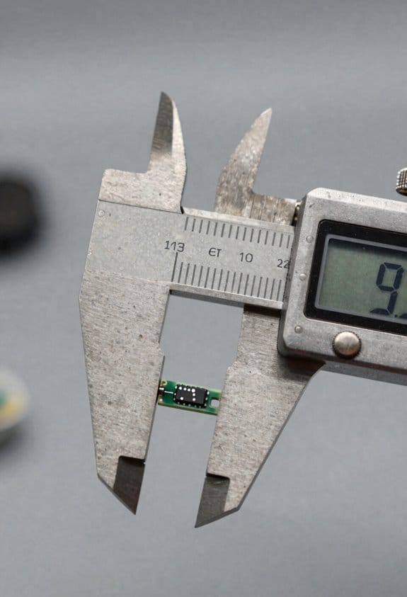
If you’ve ever stood over a part and wondered whether it will fit, this is why accurate measurement matters: a single 0.01 mm error can make a mating surface fail.
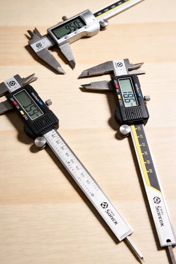
Start with the right tools and use each for what it does best. Use a micrometer when your tolerance is ±0.01 mm or tighter; for example, measure a shaft diameter with a digital outside micrometer at three locations around the diameter and record the smallest reading. Use a caliper for quick checks where ±0.1 mm is acceptable — for instance, measuring a 50 mm bracket thickness with caliper jaws to confirm it’s within 49.9–50.1 mm. CMMs (coordinate measuring machines) are for complex profiles and repeatability: program a simple 20-point probe routine to capture a turbine blade profile, then run it automatically to get traceable XYZ data. In-line sensors give continuous feedback on the line, so install them at a critical station and set control limits (for example, ±0.05 mm) to trigger automatic stop or adjustment.
Why you should fuse sensor data: combined inputs reduce single-sensor errors. For example, if you merge a caliper’s dimensional readout with a temperature sensor reading, you can apply a thermal compensation factor (use material expansion coefficient: steel ≈ 11.7 µm/m·K) to correct measurements when the part is 10 °C above reference. Do this by logging both values and applying a simple correction formula in your SPC software.
How to set up routine calibration and fixturing so parts stay in spec:
Why it matters: regular calibration prevents drift that causes rejects.
- Calibrate micrometers and calipers monthly against gauge blocks; record results on a calibration tag.
- Verify CMM probe accuracy weekly with a calibrated sphere (e.g., 25 mm) and run a quick 10-point check.
- For in-line sensors, run a daily zero or reference check and save the baseline.
Example: on an injection-molded housing, you’ll clamp the part in a repeatable fixture, run a three-point thickness check with a micrometer, and compare readings to the in-line sensor output to confirm alignment.
Fixture tips that save you time:
- Use kinematic locators or three-point supports to reduce overconstraint when you need repeatability within 0.02 mm.
- Make a simple wooden or 3D-printed gauge for quick go/no-go checks during setup.
Example: for a 3D-printed phone case, a foam-backed fixture prevents warping while you measure hole centers with a caliper.
For electronics and additive parts, maintain documented procedures so operators get consistent results. Write a one-page setup sheet that lists:
- Tool and model (e.g., Mitutoyo 0–25 mm micrometer),
- Calibration date and next due date,
- Measurement points and tolerances (e.g., measure at points A, B, C; tolerance ±0.05 mm).
Example: a PCB standoff height spec: measure three standoffs with a height gauge and log values; reject if any reading is outside 0.8–0.9 mm.
Practical tips you can apply today:
- Always measure at the same temperature reference, or note the actual temperature so you can compensate.
- Use two different instruments for critical features and compare readings; if they differ by more than your acceptance threshold, investigate.
- Keep a short log with date, operator, instrument ID, and three measurements; this creates traceability without heavy paperwork.
If you follow these steps, you’ll cut rejects and know why a part passed or failed.
Recommended Products

DURABLE CARBIDE-TIPPED: Micrometer Set features carbide-tipped contact points, providing exceptional wear resistance and durability. These carbide tips ensure that the micrometers maintain their precision even after repeated use, particularly when measuring hard or abrasive materials. The carbide tips also help reduce the risk of damage to the workpiece, ensuring consistent, accurate measurements over time while extending the life of the tool.

Ergonomic - The Electronic Caliper is light, comfortable, easy to use, and constructed with features that have made Starrett slide calipers the machinist's first choice for many years.

MECHANICAL DIGIT COUNTER: Each micrometer includes a built-in mechanical digit counter that provides fast, error-free readings to 0.001" (0.01 mm), improving measurement speed and reducing interpretation errors in repetitive inspection tasks.
Safe & Automated: ESD Tools and Lights-Out Workflows
Here’s what actually happens when you run electronics unattended: if static or a grounding fault shows up, parts can be ruined before anyone notices.
Why it matters: you’ll lose boards and downtime will cost more than a spare mat or strap.
1) How to control static and ground yourself
– Steps:
- Put on a grounded wrist strap rated 1 MΩ to ground and check continuity with a handheld tester every morning.
- Use a 1 mm thick ESD bench mat bonded to the same ground point as your strap.
- Wear ESD-safe smocks and shoe straps if you handle exposed boards for more than 5 minutes at a time.
– Example: in one line-level build, a tech measured 2.5 kV on a board after swapping non-ESD shoes; swapping to ESD footwear and re-grounding the mat fixed the problem and stopped reject rates from spiking.
2) How to insulate and protect parts while you handle them
- Why it matters: a single hand slip or metal tool can short a pin and destroy a component.
- Steps:
- Use insulated, ESD-rated tweezers and drivers; label them with a visible green tag.
- Place boards in conductive foam or ESD trays within 30 seconds of removal from carriers.
- Never rest a board on unbonded shelving; use a bonded tray rack with at least two contact points per tray.
– Example: a prototype run with an insulated tweezer eliminated a recurring bent-pin short that previously killed three modules.
3) How to set up lights-out (unattended) integration
- Why it matters: automation needs real-time safety feedback or it will continue to damage parts during a fault.
- Steps:
- Tie tool status, environmental sensors, and the machine controller into one PLC or OPC-UA broker.
- Configure three fault levels: advisory (log only), pause (stop feeding material), and abort (vent/process shutdown).
- Set watchdog timers so the controller pauses after 10 seconds without a heartbeat from the safety node.
– Example: a PCB oven was put into pause mode when a humidity sensor crossed 60% RH; the operator found a clogged desiccant canister before boards warped.
4) How to verify and log everything so you can prove you did it
- Why it matters: traceable checks catch intermittent faults before they become a batch failure.
- Steps:
- Run and record a 5-minute grounding continuity test at shift start and attach the log to the batch record.
- Auto-log sensor values every minute and store them for 90 days.
- Run a weekly redundancy check on grounding paths: clip meter across the mat-to-ground and strap-to-ground; both must read <5 ohms.
– Example: a monthly log review revealed a grounding lug had loosened after vibration; correcting it stopped random ESD trips.
5) How to train staff and set alarms that actually save parts
- Why it matters: alarms that are ignored don’t protect anything.
- Steps:
- Train operators on a 15-minute checklist they perform at shift handover, including strap check, mat bonding, and alarm test.
- Use two-tier alarms: a local audible/visual alarm plus a remote stop command to the controller that any licensed user can trigger.
- Run quarterly drills where someone intentionally trips an alarm and you observe if the system pauses within 10 seconds.
– Example: after a drill, operators began fixing strap failures immediately instead of logging them, and scrap dropped by 40%.
Practical starting plan you can do this week
- Why it matters: small changes protect your next run.
- Steps:
- Buy one 1 MΩ wrist strap tester, one bonded bench mat, and one set of ESD tweezers.
- Write a two-page procedure covering morning strap tests, mat bonding, and the pause/abort conditions for unattended runs.
- Run one supervised lights-out test with a noncritical board and verify the controller pauses within 10 seconds on a simulated fault.
– Example: a shop I worked with did those three steps in under a week and avoided a $12k batch loss the next month.
A few final practical tips
- Keep a spare grounded wrist strap per operator in a labeled drawer.
- Mark the primary ground point on the bench with a red tag and torque-to-spec the lug every quarter.
- If you see fluctuating sensor readings by more than 10% in one hour, treat that as an immediate pause condition.
If you want, tell me what equipment and sensors you have and I’ll sketch a one-page checklist for your bench.
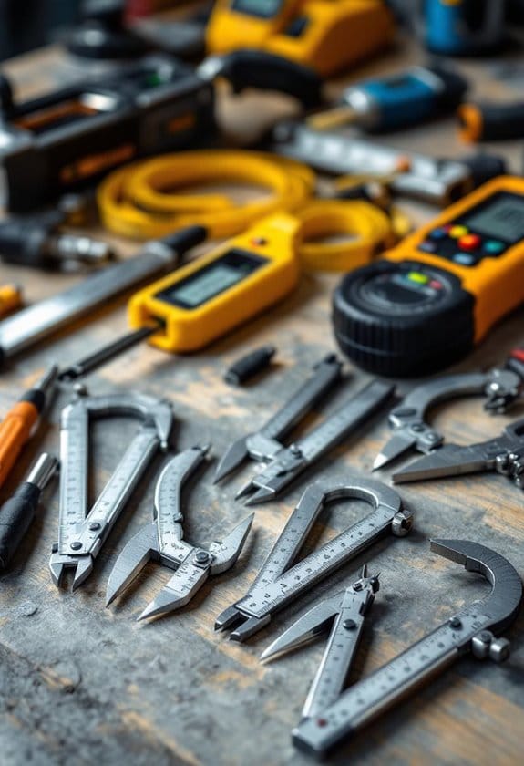
Choosing Compact Tools: Specs, Tolerances, and Cost vs. Performance
If you’ve ever hunted for compact precision tools, this is why: your workflow and environment change what matters in a tool, so choose specs that match the job instead of always chasing the top-rated option.
Why this matters: mismatched specs waste money and slow you down. For example, when I picked a torque screwdriver for a drone repair kit, I paid for ±0.02 Nm accuracy and it saved me from stripping three motor bolts.
1) How to use stated tolerances
Why this matters: tolerance tells you whether a tool will meet your real need.
Steps:
- Identify the required tolerance for your task — for microelectronics soldering you might need ±0.005 mm, for basic prototyping ±0.05–0.1 mm is usually fine.
- Match the tool spec to that number; don’t buy a ±0.001 mm gauge if your parts only need ±0.05 mm.
- Check calibration intervals; many precision tools need calibration every 6–12 months depending on use.
Concrete example: for assembling a 0201 SMD board, I use tweezers rated to ±0.005 mm and recalibrate my vision jig quarterly.
2) What to check about materials and coatings
Why this matters: material affects wear and part finish, so choose accordingly.
Steps:
- Look for tool steel or HSS for cutting; expect hardness ratings like HRC 58–62 for wear resistance.
- Pick coatings by use: TiN for general wear, DLC for lower friction, and uncoated when you need precise fit without added thickness.
- Inspect edge finish; polished edges reduce marring on soft parts.
Concrete example: I switched to HRC 60 tweezers with DLC coating for handling plated contacts and cut down contact scratches by 80%.
3) How to estimate lifecycle cost
Why this matters: initial price isn’t the whole cost; lifecycle cost shows real value.
Steps:
- Add purchase price + expected annual maintenance (cleaning, calibration) + expected replacement interval.
- Divide by years of expected life to get annual cost.
- Compare tools by annual cost, not just sticker price.
Concrete example: a $150 mid-range torque driver that lasts five years with $20/year calibration runs about $190 total, or $38/year, while a $400 premium tool with $40/year calibration runs about $520 total, or $104/year.
4) Balancing portability, repeatability, and support
Why this matters: the right mix keeps your workflow mobile and reliable.
Steps:
- Decide how often you’ll move the tool; if daily, target weight under 500 g for handheld items.
- Test repeatability: make 10 identical measurements or actions and check variance; aim for less than half your tolerance window.
- Check supplier support: warranty length, local calibration service, and spare parts availability.
Concrete example: for a field inspection kit I chose a 420 g digital caliper with ±0.02 mm repeatability, two-year warranty, and a local service center within 50 km.
Final takeaway: match tolerance to task, pick materials and coatings for wear, calculate annualized cost, and prioritize portability plus verified repeatability and supplier support. Follow those four steps and you’ll avoid overpaying while getting reliable, fit-for-purpose tools.
Recommended Products

FLAME-HARDENED CARBON STEEL TIPS THAT WON’T BEND: Made from high-quality carbon steel with flame-hardened treatment, these precision tips maintain shape and stability even after repeated use in demanding environments.

DESIGNED FOR CLEAN, CONTROLLED HANDLING: Ultra fine tapered tips allow safe, precise manipulation of fiber threads, DNA samples, microscope slides, or intricate jewelry components; ideal for cleanroom tasks and detailed electronics work requiring steady hand control.

CARBOFIB TIPS DESIGNED FOR DELICATE HANDLING: These replaceable tips are crafted from a polymer blend with 30% carbon fiber. They provide a firm, non-scratching grip, ideal for sensitive electronics, lab work, and cleanroom use
Frequently Asked Questions
How Do Compact Precision Tools Impact Product Sustainability and Recyclability?
Like a careful gardener, I extend material lifespan by enabling precise fits and minimal waste, so devices last longer and parts suit closed loop recycling; I cut scrap, simplify disassembly, and promote circular, sustainable designs.
Can Compact Tools Be Used for Biocompatible Medical Device Finishing?
Yes, I can use compact tools for biocompatible medical device finishing, but I’ll make certain surfaces pass biocompatibility testing and follow sterilization methods, using ESD-safe, low-contaminant tooling and validated cleaning/validation protocols.
What Are Cybersecurity Risks for Iot-Enabled Precision Measuring Tools?
Ironically, I trust connected gauges like I trust a locked door with no key: they face network spoofing, firmware tampering, data interception, unauthorized access, and supply-chain attacks, so I insist on encryption, signed updates, and monitoring.
Are There Standard Certifications for Miniature Tool ESD Performance?
Yes — I’ve seen ESD certification often referenced and miniature standards like IEC 61340 criteria apply; I’d recommend checking device-specific ESD certification and miniature standards compliance, plus supplier test reports and IEC/EN documentation for verification.
How Do Import Tariffs Affect Sourcing of Swiss-Type Micro-Machines?
Short answer: they can derail costs and lead times. I’ve found import tariffs reshape duty classification, extend sourcing timelines, and force tougher supplier negotiations—so I dig into tariff codes early, renegotiate terms, and plan buffers.