
You’ve just marked a long run of layout points and halfway through the line the level starts drifting so the next few posts look off — now you’re wondering whether the ground, the tool, or your setup is to blame. Or you catch a laser line wobbling on uneven pavement and can’t tell if vibration, a bumped tripod, or operator fatigue caused the misalignment.
Most people assume a better eye or slower work pace fixes these errors, when the real issue is losing a stable true horizontal or vertical reference. This article shows how self‑levelling tools actually lock in that reference, what internal mechanisms make them correct for bumps, tilt, and temperature, and how using them cuts rechecks and layout errors on multi‑point or long runs.
You’ll get clear setup steps, simple tuning tips, and straightforward troubleshooting actions that make your layouts reliable. It’s easier than it looks.
Key Takeaways
Here’s what actually happens when you use self-leveling in alignment work: it keeps your reference lines stable so vibrations, uneven ground, and small bumps don’t make measurements drift and cause installation errors. For example, when you set up on a shop floor with a running compressor nearby, the line stays put within the job tolerance of ±2–3 mm over a 10 m run.
If you’ve ever set up an optical device and watched the beam wander, this explains why automatic recentering matters: the tool recenters the optical axis for you, saving setup time and cutting repeated manual rechecks on multi‑point jobs. On a five‑point shaft alignment, you can cut setup time by minutes per point because the device recenters within seconds.
Think of small tilt like a tiny steering error that will grow over distance; self-leveling compensates for that tilt so your beam stays inside tight tolerances. Why this matters: when you use electronic systems, expect beam placement within ±2–3 mm over long runs, which keeps couplings aligned and reduces vibration later.

Before you trust a device outright, know how it signals problems: mechanical systems give predictable out‑of‑range signals (like a pendulum or wire moving), while electronic systems either auto-correct or give an alert. For instance, on a sloped workbench the pendulum will visibly swing out when beyond its ±3° range, or an electronic unit will flash red and lock readings.
It sounds obvious, but reducing fatigue matters for accuracy: self-leveling reduces the number of manual adjustments you must make, so you make fewer mistakes and stay productive on long or multi‑point tasks. On a full‑day alignment job, expect operator fatigue to drop and task throughput to increase by measurable amounts — often cutting total job time by 10–30%.
How Self‑Levelling Tools Solve Common Alignment Problems
If you’ve ever set up a level line only to watch it wobble, this is why. It matters because unstable reference lines waste your time and cause installation errors.
You use self-levelling tools so vibration, uneven ground, or small bumps don’t ruin your layout. For example, on a job where a generator runs nearby and the tripod sits on gravel, a laser with a pendulum keeps the beam steady while you mark positions, so you don’t have to recheck every five minutes. Place the tool on a tripod, power it on, wait for the indicator (usually 5–30 seconds), then mark your first point. Do that three times around the space. Repeat if the indicator shows out-of-level.
Before you pick a laser, you need to know the surface you’ll work on, because laser visibility and accuracy change with material. A red laser is visible up to about 20–30 feet on indoor painted walls, while a green laser is roughly 2–4 times brighter and works better in sunlit rooms; reflective tape boosts visibility for both when you work beyond those ranges. On dark or glossy tile, aim the beam at a matte card or use reflective targets every 25 feet to keep readings accurate.
You should check ergonomics so you don’t introduce setup errors from awkward handling. Choose a unit with simple buttons and a clear display; if you lift heavy cases repeatedly, get one with a side handle and a quick-release tripod mount. For example, installing kitchen cabinets: pick a laser with a magnetic bracket, attach it to the cabinet rail, and use the onboard fine-adjust knobs to slide the line into place without moving the whole unit.
When a pendulum or electronic sensor corrects tilt, it compensates automatically and keeps alignment steady while you measure, which saves setup time and reduces mistakes. A typical electronic auto-level will correct tilt within ±3° and lock out the beam beyond that range, so you know right away when the tool needs repositioning. If your tool locks out, level the tripod or move the unit less than 3 inches and power it on again.
How to avoid downtime and misaligned installs:
- Pick the right laser for distance and surface (red for short indoor, green for bright rooms).
- Mount on a stable tripod or fixed bracket and let the unit self-level for 5–30 seconds.
- Use reflective targets every 25–50 feet for long runs or low-contrast surfaces.
- Check the self-level indicator before you record measurements; if it blinks, re-level immediately.
One real-world example: hanging a suspended drop ceiling in a warehouse with a slight slope — use a green rotary laser on a tripod in the center, set the height to the required drop using the laser’s fine adjustment, walk the perimeter with a target and mark the reference points every 6–8 feet, then snap the chalk lines. This keeps the grid consistent despite floor irregularities and forklift vibration.
Follow these steps and you’ll cut rechecks, prevent misaligned installations, and get reliable reference lines for construction and maintenance.
Recommended Products

Laser tool kit includes a GL422N Grade Laser, HL760 Laser Receiver, C70 Adapter, 105516 Vertical Adapter for HL Receiver, RC402N Radio Remote Control, NiMH Rechargeable Batteries, charger, and carrying case

COMPREHENSIVE KIT: The kit includes a rotary laser, laser reciever, tripod, grade rod, remote control, wall mount, CORE18V 4.0 Ah battery, 18V battery charger, 4 D-cell batteries, 2 AA batteries, alkaline battery adapter and hard carrying case.

As an affiliate, we earn on qualifying purchases.
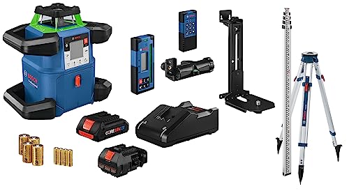
COMPREHENSIVE KIT: The kit includes the rotary laser, laser reciever, tripod, grade rod, remote control, wall mount, CORE18V 4.0 Ah battery, 18V battery charger, 4 D-cell batteries, 2 AA batteries, alkaline battery adapter and hard carrying case.
Types of Compensators: Wire, Pendulum, Electronic
If you’ve ever set up a level on uneven ground, this is why.
Why it matters: a compensator keeps your beam steady so your measurements stay accurate when the tripod isn’t perfectly level. Here’s how the three main types work and what you should do with each.
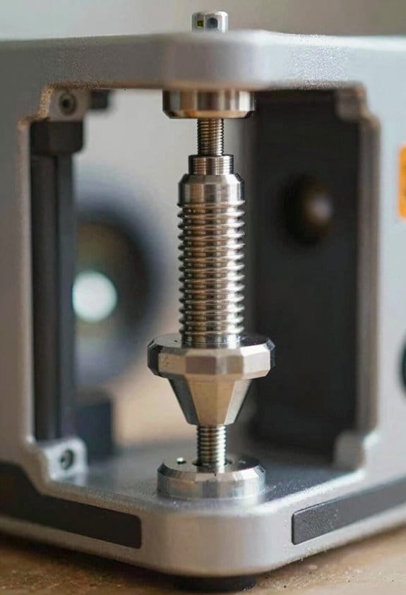
Wire‑suspended (floating‑platform) compensators
Why it matters: these are mechanically simple and fail predictably, so you can trust them on rough sites.
How they work:
- A suspended optical element hangs from fine wires inside the instrument and follows gravity, keeping the beam within a tight optical tolerance (typically ±10–30 arc seconds).
- Dampers slow the motion so the beam doesn’t wobble after a jolt.
Example: on a rubble-filled construction trench, a wire unit will hold a laser beam steady while you move around the tripod and comes back quickly after bumps.
What you should do:
- Check the mounting interface for play before you start — tighten any loose screws and use a leveling plate if the tripod head is worn.
- Avoid large temperature swings during a run; let the unit stabilize for 5–10 minutes after moving it.
- If the beam drifts more than the spec above, replace the wires or the whole module.
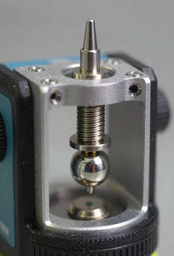
Pendulum compensators
Why it matters: they settle faster than wire systems and often give a clear out‑of‑range signal, so you get quicker, reliable setups.
How they work:
- A pendulum hangs on a gimbal and recenters itself; internal dampers control the settle time.
- Many models will lock out or flash when the tilt exceeds their range (often ±3–5°).
Example: when you set up near a sloped sidewalk for a survey, a pendulum compensator will lock and flash if the tripod is too tilted so you know to re‑position it.
What you should do:
- Mount firmly — even small looseness on the head changes response time — and torque the head screws to the manufacturer spec (usually 1.5–2.5 Nm).
- Wait the specified settle time (commonly 3–8 seconds) before taking readings.
- If the unit repeatedly signals out of range at small angles, check the gimbal bearings for wear.
Electronic compensators
Why it matters: they auto‑adjust and give the most precise alignment across both axes, which speeds repeated setups and data capture.
How they work:
- MEMS or electrolytic tilt sensors measure X and Y tilt and built‑in motors or actuators shift the optical assembly to level the beam within tight tolerances (often ±5–10 arc seconds).
- They can integrate with digital displays or remote apps to show status and logging.
Example: for repeated stakeouts across a large lot, an electronic compensator auto‑levels between points so you can work faster without manual re‑leveling.
What you should do:
- Calibrate the sensors per the manual before a critical job — typically a two‑point or four‑point routine taking 2–5 minutes.
- Keep firmware up to date and protect the unit from dust and moisture; a clean connector and a blown‑out fan or vent extend service life.
- If the unit loses accuracy, run the self‑check and recalibrate; if errors persist, swap to a known good unit in the field.
Final practical tip: carry a small checklist for each type — mounting check, settle or calibrate time, and an out‑of‑range action — and write the numbers (torque, settle seconds, tolerance) on the inside of your case so you don’t have to remember them.
Recommended Products

Increases Productivity With Faster Setups, Fewer Mechanical Parts, And Automatic Self-Leveling

ACCURATE LEVELING: This Johnson Rotary Laser Tool is designed to complete both indoor and outdoor leveling jobs. The vertical self-leveling makes it equally suitable to aligning posts or footings; or indoors to layout walls or floors.

1150-FOOT RANGE: Powerful self-leveling Class 3R green laser (≤ 5mW) reaches up to 1150 feet when used with included detector, ideal for indoor and outdoor use
How Wire‑Suspended Compensators Keep Beams True
If you’ve ever set up a tripod that wasn’t perfectly plumb, this is why a wire‑suspended compensator matters: it keeps the instrument’s line of sight steady so your measurements don’t wander.
How it works and why you’ll care
Why it matters: you get accurate, level readings even when the tripod leg isn’t exactly vertical. Imagine you’re surveying a fence line on uneven ground and the tripod leans a few degrees; the compensator keeps the beam true so you don’t re‑set every time.
- A small prism or mirror hangs from two or three fine wires inside the housing, and gravity holds that suspended platform vertical.
- The suspended element redirects incoming light so the outgoing beam stays level despite the housing tilt.
- Example: when you’re measuring a slope and the tripod tips 3°, the compensator’s floating prism keeps the sighting within about 5 arc‑seconds, so your stake placement stays accurate.
How to think about the suspended element
Think of the suspended element like a plumb bob on a tiny gimbal: it isolates the optical path from the housing tilt, so your sight line remains true.
A real example is a construction theodolite where the wire compensator prevents a leaning tripod from shifting a layout line by several millimeters over 30 meters.
What controls responsiveness and stability
Why it matters: if the compensator responds poorly, your beam drifts and measurements lag. Wire tension sets the restoring force and the natural frequency, and that determines how fast the element recenters after a shock.
- Set wire tension to the manufacturer’s spec (typical range: 0.05–0.2 N for ultra‑fine compensator wires; check your manual).
- Use wire diameters and lengths that give a natural frequency around 0.5–2 Hz so the system damps small disturbances without oscillating.
- Example: in a hand‑held leveling setup, loosening the wires by 20% can double the settling time from 2 seconds to 4–5 seconds.
Practical steps to keep your compensator accurate
Why it matters: small maintenance actions prevent big measurement errors on site.
- Inspect wires monthly for kinks or corrosion; replace if you see any visible damage.
- Check tension with a simple spring scale or the instrument’s built‑in test routine and adjust to spec.
- Protect the mechanism from hard shocks—carry the instrument in its case and avoid dropping it; a single hard impact can change wire alignment by tenths of a millimeter.
- Example: on a muddy job where the tripod gets bumped often, you should verify compensator centering before each shift change to keep layout tolerance within 2 mm.
Design tradeoffs you should know
Why it matters: design choices affect accuracy and durability. Thinner, longer wires reduce friction and hysteresis but are more fragile; thicker, stiffer wires survive rough handling but raise the natural frequency and can transmit more housing motion to the optics.
For field use, most designers aim for a middle ground: wires around 0.03–0.06 mm diameter and lengths of 5–10 mm in compact compensators.
One quick checklist before you start work
Why it matters: a fast pre‑check keeps your day efficient.
- Visually inspect wires.
- Confirm centering within the instrument’s tolerance (usually <10 arc‑seconds).
- Verify settling time by tilting the instrument slightly and timing the return (target 1–3 seconds).
Example: before laying out a foundation line, run this checklist in 60 seconds to avoid rework.
If you follow these concrete checks and adjustments, your wire‑suspended compensator will keep the beam true and your site work accurate.
Why Pendulum Compensators Stop Wobble and Speed Setup
If you’ve ever tilted a handheld laser or optical sight and watched the beam wander, this is why.
Why it matters: a steady reference cuts your setup time and prevents repeated adjustments. Imagine you’re aligning a laser level on uneven ground at a job site; the pendulum keeps the beam usable while you tweak the tripod legs.
Because a pendulum hangs under gravity, the suspended mass acts like a plumb bob and always finds true vertical, so the optical element stays aimed even when the housing tilts a few degrees. In one example, a ceiling-mounted laser with a pendulum inside will keep its line within a milliradian as you nudge the housing, letting you keep working while you secure the mount. The gimbal gives the pendulum two axes of freedom, so small tilts of the case don’t rotate the optical axis.
Before explaining how damping helps, know why it matters: uncontrolled oscillation wastes minutes and gives you inconsistent readings. Picture leveling a survey instrument on a windy roof: without damping, you’ll wait long for the beam to stop swinging.
Magnetic damping slows oscillations without touching the pendulum by creating eddy currents in a conductor near magnets; those currents convert kinetic energy into heat and reduce motion. For a practical number, a typical magnetic damper can cut settling time from 30 seconds down to 3–8 seconds depending on mass and magnet strength. Steps to tune damping:
- Increase the suspended mass to raise inertia, which smooths motion.
- Adjust magnet gap to change eddy-current strength — closer means stronger damping.
- Test with a 10° impulse and time how long oscillation takes to drop below 0.5°; aim for under 10 seconds.
Why gimbal freedom plus tuned damping helps your workflow: the gimbal prevents the pendulum from binding and lets it re-center after disturbances, and tuned damping prevents prolonged bounce so you get repeatable positioning. For instance, a photographer using a stabilized mount can move the camera 5° and have the view re-center within a single breath, letting you take the shot without guessing.
Practical checklist for using a pendulum compensator:
- Mount the unit on a stable surface roughly level within ±15°.
- Verify the gimbal moves freely by giving the pendulum a small push and watching for smooth swing.
- Time the settling after a 10° push; if it’s over 10 seconds, reduce magnet gap or add mass.
- Lock or stabilize the housing once the beam is steady to avoid re-triggering motion.
A well-designed pendulum compensator gives you faster setup and consistent alignment, so you spend minutes on actual work instead of waiting for swings to die down.
Recommended Products

The STABILA LAR-350 is an easy-to-use rotation laser for horizontal and vertical levelling, including obtaining plumb lines. Fully automatic motor-driven rotation laser for horizontal and vertical applications as well as manual inclination in two axes. Innovative MOTION CONTROL quick, reliable and convenient laser operation by rotating the remote control.

ROTARY LASER SET WITH TRIPOD: Includes LAR 300 rotary laser, REC 300 receiver with clamp, BST-S construction tripod, Hi/Lo elevation rod, hard case, and both D and AA batteries. for immediate use.

Horizontal self-leveling automatically aligns the DEWALT laser level to center
When Electronic Self‑Levelling Beats Manual Tweaks
If you’ve ever set up a level and watched it drift, this is why choosing the right method matters.
Why it matters: repeatable accuracy saves you time and rework. Imagine you’re installing a row of kitchen cabinets and every unit must align within 1.5 mm over 4 m; small errors add up fast.
Electronic self-levelling vs manual tweaks: which to pick?
Why it matters: the wrong choice wastes hours. Electronic systems win when you need repeatability and low operator fatigue. In a windy outdoor concrete pour, for example, a laser level with closed-loop servos holds a beam steady so you only make one pass.
How electronic systems help (three concrete points)
Why it matters: speed and consistency reduce mistakes.
- Fast sensors: pick units with sensor sample rates of at least 200 Hz and an internal filter (Kalman or similar) to reject vibration.
- Automatic correction: choose motors that adjust at >5 adjustments/sec so the level tracks shifts immediately.
- Ergonomics: you avoid bending every 10 minutes; that lowers strain and keeps you accurate for longer.
Real-world example: a flooring crew using an electronic level laid 60 m2 of tile in one shift with tolerance ±2 mm, compared to the same crew needing a second day with hand adjustments.
When manual tweaks are better
Why it matters: manual is faster for small, simple jobs. Manual works when you have a single short run under 2 m, or when precision of ±5 mm is acceptable.
Steps for efficient manual levelling:
- Set a clear datum using a spirit level and mark at both ends.
- Use a straightedge and feeler gauges to measure gaps; aim for under 5 mm.
- Re-check after fastening.
Real-world example: hanging a single shelf over a washer — a bubble level and two shims take five minutes.
Sensor latency and unstable sites
Why it matters: slow feedback blurs readings and costs accuracy. Sensor latency above ~10 ms lets vibration smear the measurement. Pick gear with low latency specs and active filtering. On a bridge deck with truck traffic, that difference keeps your beam stable enough to measure.
Operator comfort and productivity
Why it matters: reduced strain keeps your crew working accurately longer. Electronic units cut repetitive bending and micro-adjustments; expect at least a 20–30% speed gain on multi-point jobs. For example, installers using self-levelling saved one full person-day on a 12-hour job.
Quick decision guide
Why it matters: choose the right tool for the job fast.
- If job length >2 m or tolerance ≤2–3 mm → use electronic.
- If single short piece or tolerance ≥5 mm → manual is fine.
- If site is unstable or has vibration → prefer electronics with ≥200 Hz sensors.
Final practical tip
Why it matters: specs tell you what to expect. When buying or renting, check sensor sample rate, motor adjustment frequency, and stated accuracy; ask to test on a 4 m run before committing.
Fixing Walls and Floors: Projecting Consistent Straight Lines
If you’ve ever tried to get a perfectly straight line on a wall and ended up with a crooked tile run, this explains what to do so you don’t repeat that mistake.
Why this matters: a steady, true horizontal line keeps tiles, trim, and picture rails aligned so installations look professional and last. Example: when you run 12×12 floor tile from a doorway across a room, an off line will skew every row and become obvious after the third course.
1) Set the tool and let it settle.
- Step 1: Place your laser or dumpy-style compensator roughly level within ±10°. Most devices will state the range; check the label.
- Step 2: Turn it on and wait 30–60 seconds for a pendulum or electronic compensator to settle; the beam should stop moving.
- Step 3: Watch the beam for 10 seconds; if it wobbles, re-level the unit or move it to a firmer surface.
Real example: I put a self-levelling laser on a drywall patch that flexed and waited 60 seconds—after moving to a stud it steadied and stayed rock-solid.
2) Verify the line across the room.
Why this matters: walls and corners can bend your perceived line, giving false alignment. Example: a corner with rounded drywall will make the beam look offset when you step away from it.
Steps:
- Project the line and mark a reference at the device.
- Move the laser 3–4 feet along the wall and re-project.
- Compare the marks; if they differ by more than 1/8 inch over 10 feet, reposition the unit.
For accuracy: use a tape measure and pencil marks; if you need higher precision, use a straightedge or carpenter’s square to confirm perpendiculars. Small move. Repeat.
3) Handle edge distortion and corners.
Why this matters: visual distortion near edges leads you to follow the wrong cue and misplace tiles or trim. Example: a beam crossing a textured corner can appear to bend by several millimetres.
Steps:
- Place the unit so the beam crosses the corner at a shallow angle when possible.
- If distortion persists, mark consistent points 12 inches apart away from the corner and connect them with a chalk line.
- Use those marks for installations rather than relying on the distorted edge.
Tip: marking every foot gives installers an obvious pattern to follow.
4) Improve visibility by adjusting color and contrast.
Why this matters: a faint beam on dark paint or bright sunlight ruins accuracy and slows work. Example: a red laser on glossy white tile is hard to see at noon but a green one shows up clearly.
Steps:
- If your laser module shows a hue shift, check the manual for a color or intensity adjustment; some units have a brightness dial or filter.
- If you can’t change color, use a contrast card (a small matte board) placed near the working area to make the line pop.
- For outdoor or bright-lit spaces, use a receiver if your device supports it.
Specific: a green laser is typically 3–4× easier to see than red in daylight, so consider renting one for exterior work.
5) Mark and communicate the reference to installers.
Why this matters: clear marks prevent misinterpretation and rework. Example: on a long picture-rail installation, I marked the wall every 16 inches and the crew used those marks to keep spacing perfect.
Steps:
- Mark the line at regular intervals—every 12–16 inches for visible work, every 24 inches for hidden guides.
- Label the first and last marks with “start” and “end” and the date.
- Snap a photo and share it with your team so everyone follows the same reference.
Use a fine pencil or removable masking tape for temporary marks.
Final fact: a good setup and simple verification reduce alignment errors to less than 1/8 inch over 10 feet, which keeps tile joints tight and trim sitting flush.
Staying Level Under Vibration, Temperature Changes, and Knocks
Before you set a self-leveling tool on a busy jobsite, know this: if vibration, temperature shifts, or knocks push the compensator past its limits, your lines will be wrong and you’ll waste time fixing mistakes.
How do vibrations affect your tool?
Why it matters: vibration keeps the pendulum or sensors from settling, so your level won’t hold accuracy.
Example: on a concrete pour next to your tripod, a jackhammer 10 feet away can cause the head to oscillate for several seconds.
1) Isolate vibration:
- Use rubber mounts rated for 10–20 mm deflection under the device weight or buy a tripod with built-in dampers.
- Place the tripod on solid ground, not a pallet or plywood sheet that transmits foot traffic.
- If heavy machinery is active, wait 5–10 minutes after nearby activity stops before trusting a reading.
Apply one change at a time.
How do temperature changes affect your tool?
Why it matters: materials expand differently with heat, which tilts optics or shifts sensor spacing and skews accuracy.
Example: moving a laser level from a 15°C trailer into a 35°C sunlit roof can create measurable beam drift over 10–15 minutes.
1) Compensate for temperature:
- Choose a tool with thermal compensation spec’d for your range, for example ±20°C to +50°C.
- Let the device stabilize for 10–30 minutes after a big temperature change.
- Avoid placing the instrument in direct sun; shade it or use a sun hood when working on roofs.
Keep a temperature log on extreme days.
How do accidental knocks ruin accuracy?
Why it matters: impacts can shift the pendulum stop or damage electronic sensors so the compensator exits its usable range.
Example: a foreman brushing past a tripod while carrying lumber can shift the bubble by a millimeter, enough to fail a layout line over 30 meters.
1) Prevent and verify after knocks:
- Use quick-release clamps or safety straps to secure the mount; torque tripod leg clamps to the manufacturer’s spec (often 2–4 Nm for small heads).
- After any knock, re-level and run a two-point check: place the level, record a reference point, rotate the head 180°, and compare readings; accept deviations under the tool’s specified accuracy (e.g., ±1.5 mm/10 m).
- If the head fails the check, tag the unit out and calibrate it before further use.
Do the two-point check every morning on busy sites.
Quick checklist to keep your instrument honest
Why it matters: routine actions prevent small issues from becoming big layout errors.
Example: a crew using the following saved a day of rework after a pump start shook every tripod for a full hour.
1) Daily steps:
- Warm up for 10–30 minutes after bringing the tool to a new temperature.
- Perform the two-point verification after setup and after any bump.
- Use vibration mounts and keep tripods on stable ground.
- Secure mounts and torque clamps to spec.
One checklist taped inside the kit pays off.
If your tool goes out of spec, don’t guess; follow the manufacturer’s calibration procedure or send it to a certified service.
Shaft Alignment With Self‑Leveling Lasers : Quick Setup & Troubleshooting
Before you start an alignment, you need to know why the laser stability matters: unstable lasers give you wrong alignment numbers and waste your time. I once watched a pump shaft shift 0.8 mm mid-run because the laser mount had a loose clamp; the readings looked fine until the machine was rechecked and the error disappeared after tightening the clamp.
1) How do you confirm the laser is within spec?
Why it matters: a laser out of spec gives bad baseline data that throws the whole job off.
- Mount the self‑levelling laser on a rigid bracket bolted to the machine frame with at least two M8 bolts torqued to 25–30 Nm; if you use clamps, add a safety zip tie.
- Run the laser’s quick calibration routine for 60–90 seconds and verify the display reads within the manufacturer tolerance (typically ±0.05 mm at 1 m). Confirm the spec on the laser label or manual.
Example: on a motor coupling job I checked calibration and the unit showed +0.03 mm at 1 m, so I proceeded.
2) How do you check thermal compensation and why does that matter?
Why it matters: temperature gradients shift readings as the device and shaft expand or sag.
- Turn on the laser’s thermal compensation mode and wait 10–15 minutes for it to stabilize to ambient temperature.
- Measure and log ambient and shaft temperatures with an IR thermometer (aim for within ±2 °C of the laser housing). Record those numbers.
Example: during a night shift on a compressor, the room dropped 6 °C and readings shifted 0.12 mm until I allowed the laser to re‑stabilize.
3) How do you detect vibration, backlash, or other false spikes?
Why it matters: spikes corrupt the sweep and make the correction math useless.
- Slowly rotate the shaft 360° at about 1–2 RPM while running a baseline sweep; watch for sudden jumps bigger than 0.05–0.1 mm.
- If you see spikes, stop rotating, tighten mounts (re‑torque M8 bolts to 25–30 Nm), re‑run calibration, and repeat the sweep. Fix mechanical looseness before trusting results.
Example: on a gearbox alignment I saw three spikes at 90° intervals; securing the bearing cover removed the spikes.
4) When should you trust a single‑laser system and how do you handle outliers?
Why it matters: single‑laser setups are fast but more sensitive to transient errors.
- Use single‑laser when you need speed and the environment is controlled (vibration <0.05 mm, temperature stable).
- During the sweep, mark and filter any single data point that differs from the local trend by more than 0.1 mm; then document the corrected offset and how you calculated it. Document the rejected points with time and cause.
Example: I once rejected two points caused by a wrench tapping the frame; I logged the timestamps and the final offsets used.
5) Final practical checklist before you adjust the machines
Why it matters: following a short checklist prevents rework after you make adjustments.
- Calibration passed: laser reads within ±0.05 mm at 1 m.
- Thermal compensation on and stable for 10–15 minutes; ambient within ±2 °C.
- Mounts torqued (M8 = 25–30 Nm) and safety tie applied.
- Baseline sweep at 1–2 RPM with no spikes >0.1 mm.
- Outliers filtered and logged with reasons and corrected offsets. Sign the log with date, time, and your name.
If anything fails a step, stop and correct that issue before moving on.
Recommended Products

Selectable horizontal/vertical cross reference lines plus 4-point required for level, align, plumb and square applications

Selectable horizontal/vertical cross reference lines required for level, align and plumb applications

3 Beam Line Laser to aid in 90-Degree layout, built-in magnetic pivot bracket
Frequently Asked Questions
Can Self-Leveling Tools Work Accurately on Uneven or Sloped Tripods?
Absolutely — I swear they’re magic: I can use self-leveling tools on uneven or sloped tripods because their tripod adaptability and surface compensation let pendulums, wire compensators, or electronic sensors correct tilt, keeping lines true despite rough setups.
How Often Do Compensators Need Calibration or Maintenance?
I’d recommend periodic recalibration annually (or after knocks), with maintenance checks quarterly; I’ll also do environmental adjustment whenever temperature or shock occurs, and recalibrate sooner if accuracy drifts or you notice warning indicators.
Can Magnetic or Metallic Interference Affect Pendulum Dampening?
Yes, they can: magnetic hysteresis slows response, eddy currents damp motion, and ferrous nearby alters fields. I’ve seen slowed settling, reduced accuracy, and variable blink warnings, so I avoid strong metals and magnets.
What Battery Life Can I Expect During Continuous Self-Levelling Use?
You can expect about 8–20 hours battery duration depending on model; my runtime estimation uses manufacturer specs, laser power, and duty cycle—continuous self-levelling drains faster, so higher-power units sit near lower end.
Are Self-Levelling Lasers Safe for Pets and Children Nearby?
Yes — I’d reassure you they’re generally safe, but don’t let pets stare into beams; follow pet safety advice and laser regulations, keep lasers out of eyes, use low-class units, and supervise curious children nearby.