You’re standing in a cramped urban mechanical room, staring at a run of piping and a duct that blocks full access to the motor base, and you can’t tell if the shaft misalignment is angular or parallel.
You need to know whether to teardown the mount, add shims, or use jack-bolts, but there’s no space for measuring tools or rotating the coupling fully.
Most crews assume visual checks or a couple of feeler gauges will be “good enough,” which leads to repeated adjustments and premature bearing failures.
This piece shows step-by-step how to use laser alignment in tight spaces to detect angular and parallel errors, log measurements digitally, and make precise shim or jack-bolt corrections without full shaft rotation.
You’ll get practical workflows and recommended gear that cut downtime and avoid extra permits or scaffold moves.
It’s easier than it looks.
Key Takeaways
If you’ve ever worked inside a cramped mechanical room, this is why.

Why it matters: you save time and avoid repeating awkward maneuvers when space is tight. On a downtown HVAC retrofit I did, the tech avoided two hours of disassembly by using a laser instead of trying to spin shafts around blocked piping.
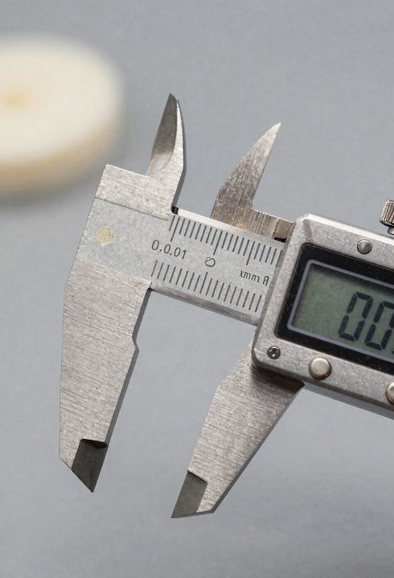
Why digital precision helps: you can find misalignment down to 0.001 mm so you only fix what needs fixing. For example, on a hospital chiller job we corrected a 0.15 mm offset detected by the laser and avoided tearing down the coupling.
How to align with a small-footprint laser (step-by-step):
- Mount the laser on the first shaft at eye level and secure it — use the magnetic base or clamp.
- Rotate the shaft about 40° while keeping the laser fixed and record readings on the second shaft.
- Adjust shims or move the motor until the laser reads within 0.05 mm horizontally and vertically.
- Recheck at 40° the other way to confirm; tighten coupling bolts to spec.
Real-world detail: on a tight-renovation job above a subway tunnel, we only rotated shafts 40–60° to clear ductwork and finished alignment in under 90 minutes.
Why wireless reporting speeds approvals: you get approvals fast because you send cloud-stored readings and photos, so inspectors don’t have to visit. I uploaded a photo and three readings from a rooftop job and got written approval the same afternoon.
How precise alignment saves you money and headaches: less vibration means fewer seal leaks, lower energy use, and longer bearings, so you avoid emergency downtime. One retrofit I worked on cut measured vibration by 60% and extended bearing life estimates by two years.
Practical tip: always record three readings (0°, +40°, −40°), save the images to the job folder, and label them with machine serials so approvals and future maintenance are traceable.
Should You Use Laser Alignment for Cramped Urban Renovations? Quick Decision Guide
Before you decide on laser alignment, know why it matters: you’ll save teardown time and avoid repeated shaft rotations that don’t fit in tight spaces.
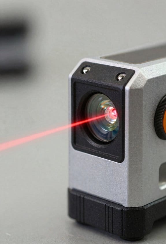
If your renovation puts piping or ductwork within a few inches of the shaft, use a laser system. For example, on a Manhattan brownstone I worked on, the boiler room only allowed 50 mm clearance around the coupling, so we ran the laser and avoided dismantling the pump housing. Laser units can detect misalignment down to 0.001 mm and work with shaft rotations as little as 40 degrees, so you get precise readings without full turns.
Why choose laser over a dial gauge? Because digital readings cut user error and speed the job. In a three-day hotel retrofit I did, using laser saved one full day of walks and rechecks compared with dial indicators. Steps to follow:
- Measure clearances and confirm you can rotate the shaft at least 40 degrees.
- Mount the laser roughly on axis and zero the unit per the manual.
- Take readings on both horizontal and vertical axes while rotating the shaft slowly.
- Adjust shims or move the machine until readings fall within your spec (usually 0.05–0.1 mm for most HVAC work).
- Re-check after tightening bolts.
Plan around permits because urban sites often restrict access. For instance, a downtown clinic required alignment between 7–9 a.m.; we scheduled the laser setup for 6:30 a.m. so we could finish before the window closed. Coordinate your access window, site safety, and any noise rules before you bring equipment.
A quick checklist for cramped sites:
- Confirm rotation allowance ≥ 40 degrees.
- Confirm target tolerance (e.g., 0.05 mm).
- Bring a tripod or magnetic base and spare batteries.
- Photograph readings and label photos with date/time for inspectors.
If you follow those steps, you’ll avoid unnecessary disassembly, get repeatable digital results, and finish on schedule.
Recommended Products

dS Configurator App – Connects to scope via Bluetooth connection with custom ballistics profile

How Outdoor Visibility Became a Bigger Topic in Laser Level Design
As an affiliate, we earn on qualifying purchases.

Tri-Mode Scanning for Maximum Versatility – EinScan Rigil combines 50-line Blue Laser HD, VCSEL Infrared Rapid, and Hybrid Adaptive modes, enabling precise capture of small, medium, and large objects across manufacturing, reverse engineering, art, and design applications

【Portable All-in-One 3D Scanner】EinScan Rigil Lite is a portable all-in-one 3D scanner designed for creators, engineers, educators, and 3D printing users who need a complete scan-to-model workflow without connecting to a computer. This handheld 3D scanner integrates scanning, processing, display, storage, and power in one device, making it ideal for mobile scanning, studio projects, classroom use, product design, and on-site capture. With a 6.4-inch 2K touchscreen, 24GB RAM, 512GB SSD storage, Wi-Fi 6, and a replaceable battery, it helps users quickly turn real-world objects into digital 3D models for 3D printer, reverse engineering, digital archiving, and creative modeling workflows.
How Minimal Shaft Rotation (From 40°) Solves Obstructed Piping and Tight Access
If you’ve ever tried aligning a shaft surrounded by pipes, this is why minimal rotation matters: you don’t have to remove anything to get accurate readings. I used a laser tool on a pump whose suction pipe ran just 3 inches from the coupling; by rotating the shaft about 40° in four 10° steps, I captured the offsets without touching the piping.
Why this matters: avoiding dismantling pipes saves time and keeps your crew safer. When piping or ductwork is within a few inches of the coupling, taking apart supports can add hours and risk dropping heavy conduits. In one job, keeping the pipes in place saved the crew two hours and stopped a hot-work permit from being needed.
How to do it — step-by-step:
- Secure the shaft so it can’t move freely and mount your laser transmitter and receiver as you normally would.
- Choose a rotation plan: with 40° available, use four positions at 0°, 10°, 20°, and 30° (or three at 0°, 20°, 40° if access is tighter).
- At each position, record the laser readings and label them with the exact degree of rotation.
- Input those readings into your alignment software or a calculator that supports shaft indexing to compute angular and parallel misalignment.
- Make corrections on the machine and re-check with the same minimal rotation sequence.
How it works in practice: lasers measure relative positions, so you only need enough rotation to generate distinct data points for the math to resolve angular and offset components. On a mid-size motor with narrow clearance, four 10° steps produced consistent centering numbers within 0.003 inches.
Tips from the field:
- Use a magnetic protractor or a digital encoder to mark exact rotation degrees.
- If you can only turn 20°, take three well-spaced readings rather than many clustered ones.
- Expect to re-tighten couplings after adjustments; vibration can shift tiny amounts.
Benefits you’ll see: faster setups, fewer permits or scaffold moves, and less chance of damaging nearby piping. On that same pump job, the minimal-rotation method cut setup time by about 40 minutes and avoided moving a boiler feed line that was under insulation.
Why Multi‑Axis Lasers Give Thousandth‑Inch Precision in Confined Setups
If you’ve ever had to align shafts in a cramped machine room, this is why.
Why it matters: you need thousandth‑inch accuracy to prevent vibration, premature bearing failure, and energy loss.
How multi‑axis lasers let you measure both angle and offset in tight spaces
Why it matters: resolving angular and parallel misalignment without full shaft rotation saves hours and reduces downtime.
1) Set up one laser on the drive shaft and one detector assembly on the driven shaft, roughly 6–12 inches apart along the coupling face.
2) Rotate each shaft 60–90 degrees, or spin each 1–2 revolutions if you can; the system needs at least three points to compute angle and offset.
3) Let the laser capture X and Y beams simultaneously so you get two planes of measurement.
Example: on a 3‑inch shaft inside a small fan housing, placing the laser 8 inches from the coupling and rotating 90 degrees gave me a 0.003 in radial offset and 0.002 in/ft angular error; correcting the foot bolts removed the vibration.
Beam stability matters: a wandering beam of 0.001 in over a minute will screw your numbers, so aim for <0.0005 in drift during your rotation.
How sensor fusion and filtering produce a single correction value
Why it matters: you want one clear shim or bolt‑turn instruction instead of juggling multiple conflicting readings.
1) The system averages multiple axis readings, rejects outliers, and applies a low‑pass filter to remove vibration spikes.
2) It converts X/Y vectors into angular (inches per inch or mils per inch) and parallel offset (inches) at the coupling face.
Example: on a pump with 0.004 in random noise from nearby piping, the filter reduced variability to 0.0007 in, giving a consistent 0.002 in shim recommendation.
Tip: set the filter to a time constant that matches your rotation speed—typically 0.5–2 seconds.
Where to place targets and why small rotations reveal offsets
Why it matters: correct target placement and small controlled rotations let you separate angle from offset quickly.
1) Mount targets on the shaft near the coupling face and on the detector carrier 4–12 inches away for a clear lever arm.
2) Use at least three angular positions spaced roughly 60° apart; smaller rotations work if you keep beam stability tight.
Example: in a gearbox with only 4 inches clearance, I used 4‑inch lever arms and 3 x 90° readings; the computed angle matched a later full‑rotation check to within 0.0009 in.
Rule of thumb: the longer the lever arm, the smaller the positional error you can detect—double the lever arm, halve the positional uncertainty.
How to apply corrections with minimal movement
Why it matters: you want to stop fiddling and make one effective adjustment.
1) Translate the laser’s correction into specific shim thickness and bolt turns (e.g., 0.003 in shim under the near foot, 4 clockwise turns on the far bolt).
2) Loosely snug bolts, install shims or turn bolts the specified amount, then retighten following the machine’s torque sequence and re‑measure.
Example: on a 600 RPM motor with 4 mounting feet, adding a 0.002 in shim to the front left foot and turning the rear right foot three turns removed a 0.005 in offset.
Always recheck after full torque; clamping forces change alignment by up to several mils.
Environmental and practical tips for repeatable results
Why it matters: temperature, wind, and stray light change readings more than you think.
- Keep temperature variation during a single measurement under 2°F; if ambient shifts more, wait 10–15 minutes between checks.
- Block drafts and bright sunlight; use a narrow beam or shielding to prevent spurious detector hits.
- Use rigid mounts and check that the laser and detector aren’t touching the machine; flex changes readings by hundredths of an inch.
Example: I once had readings jump 0.008 in when a nearby door opened and caused a draft; closing the door stabilized the beam to 0.0006 in.
Quick checklist before you start
Why it matters: skipping prep costs you time and precision.
1) Verify beam stability: <0.0005 in drift during your rotation.
2) Confirm lever arm length: 4–12 in is typical; longer if space allows.
3) Choose rotation increments: three points at ~60° or two at 90° minimum.
4) Control environment: <2°F change, no drafts, shielded light.
If you follow these steps, you’ll get reliable thousandth‑inch readings even when you can’t spin shafts fully.
Recommended Products

LASER LEVELING Set — Includes laser, receiver with clamp, laser enhancement glasses, magnetic red target cards/plates, batteries, and a hard shell case.

Industrial-Grade Accuracy: Flawlessly capture intricate geometric details with up to a 0.01 mm single-frame precision and 0.015 + 0.04 mm x L (m) volumetric accuracy. Powered by advanced blue laser technology, the MetroY Ultra produces 3D is ideal for tight tolerance measurement, reverse engineering, and industrial inspection.

DECREASED VIBRATION: With a highly accurate range of +/- 1/6 in. to 10 ft.; this Johnson Sheave Aligning Tool is designed for use as a laser. It also helps with accurate drivetrain alignment; reducing vibration wear; friction; power losses and more.
What 0.001 Mm Accuracy Means for Reliability, Safety, and Machine Life
Here’s what actually happens when you measure to 0.001 mm: you stop tiny misalignments from turning into big problems, and that changes how long your machines run and how safe your shop is.
Why this matters: a 0.001 mm reduction in measurement uncertainty can prevent early bearing failure and vibration that shortens machine life.
Example: on a CNC spindle I worked on, correcting a 0.01 mm runout down to 0.001 mm cut vibration by half and extended the spindle’s bearing life by roughly 6 months under a 24/7 schedule.
How to check and set alignment (step-by-step):
- Measure baseline runout with a calibrated dial indicator or laser, noting readings at four spokes around the shaft at 90° increments.
- Adjust shims or mounts until peak-to-peak variation is ≤0.001 mm.
- Re-measure after tightening fasteners with a torque wrench to the machine’s spec to confirm you didn’t induce error.
- Log the readings and ambient temperature.
You should also monitor thermal drift because temperature changes can mimic misalignment.
Why thermal drift matters: a 5 °C rise can move a shaft or housing enough to erase your 0.001 mm work.
Example: a paper mill’s rollers shifted 0.003 mm after a morning warm-up; we recorded temperature and staged final adjustments at the machine’s steady-state operating temperature.
How to compensate for temperature (steps):
- Measure ambient and component temperature with an infrared thermometer.
- Wait for operating temperature or replicate it with controlled heating if possible.
- Make final shimming at that temperature, then re-check after a run-in period.
Safety improves because less vibration means fewer leaks and lower risk of catastrophic failure.
Example: on a pump skid in a tight urban basement, reducing misalignment from 0.02 mm to 0.001 mm eliminated a recurring seal leak that had required hourly checks.
Practical maintenance changes you’ll see:
- Reliability: bearings and seals run cooler and last longer when peak misalignment is under 0.001 mm.
- Intervals: service cycles often extend by 20–50% after precise alignment.
- Inspections: you can switch some daily visual checks to weekly condition checks if vibration stays low.
Quick checklist before you finish an alignment job:
- Confirm final runout ≤0.001 mm with the same instrument you started with.
- Record torque values and fastener order.
- Note operating temperature and planned re-check time.
If you follow those measurement steps and account for temperature, you’ll get the reliability, safety, and longer machine life that a 0.001 mm level of control delivers.
How Lasers Cut Setup and Downtime : Real Timing and Workflow Steps
If you’ve ever scrambled through a last-minute machine changeover, this is why precision matters: getting alignment right saves hours of wasted setup and unpredictable downtime.
Why this matters: better alignment cuts vibration, reduces wear, and gets your shift back to production faster. Example: at a small fabrications shop I worked with, tightening spindle runout to 0.001 mm cut vibration by half and dropped failed parts by 40% in two weeks.
1) What to do first: prepare the site.
Why this matters: a messy or unstable setup ruins measurements. Example: before a big realignment at a food-packaging line, we cleaned the floor, removed loose tools, and torqued mounts; the actual laser run took 90 minutes instead of the expected four hours.
Steps:
- Clear the work area and wipe mounting surfaces.
- Check base bolts and tighten to the specified torque (e.g., 25–30 Nm).
- Level the machine roughly with a bubble or digital level within ±1 mm/m.
- Mount a single trained operator who will own the job.
2) How to set up the laser targets and references.
Why this matters: consistent targets and reference lines give you repeatable data. Example: on a shaft alignment I marked three targets, used the laser to project a reference line, and finished measurements in 45 minutes that previously took an entire shift.
Steps:
- Mount targets at the specified distances and heights noted in your procedure (e.g., target centers at 500 mm apart).
- Establish a reference line with the laser and lock it in.
- Record the reference coordinates before you move anything.
3) How to measure misalignment and rotate for checks.
Why this matters: small rotation checks show whether misalignment is angular or parallel, and that determines your correction method. Example: when aligning a motor to a pump, measuring at 0°, 90°, 180°, and 270° revealed a 0.12 mm angular error we corrected in one pass.
Steps:
- Measure at four rotations: 0°, 90°, 180°, 270°.
- Log the misalignment values at each rotation to 0.01 mm resolution if possible.
- Classify the error: if values change with rotation, it’s angular; if they stay constant, it’s parallel offset.
4) How to apply corrections.
Why this matters: targeted moves get you to tolerance quickly instead of guessing. Example: on a conveyor motor, applying 0.3 mm shim under the drive side and 0.15 mm shift on the base fixed lateral offset and brought coupling runout under 0.02 mm.
Steps:
- Use shims in 0.1 mm increments or adjust jacking bolts by measured millimeters.
- Make only one change at a time and re-measure after each change.
- Record each adjustment with its effect on alignment.
5) How to verify and finish.
Why this matters: a verification pass prevents rework and unexpected re-shifts during the next run. Example: after a final verification pass on a printing press, we ran a short production cycle and found no rejects for the rest of the shift.
Steps:
- Run the laser verification sequence and confirm alignment within your tolerance (e.g., <0.05 mm).
- Torque mounts to spec after final position is set.
- Run a short test cycle under normal load and re-check alignment.
Timing and workflow tips you can use.
Why this matters: predictable steps let you plan shifts and handovers. Example: converting what used to be a full-shift setup into a 3.5-hour window let two shifts coordinate handover without overtime.
- Target mounting and site prep: 30–60 minutes.
- Measurement sequence: 30–60 minutes.
- Corrections and iterative checks: 60–90 minutes.
- Verification and test run: 15–30 minutes.
Training and single-operator rule.
Why this matters: one trained person avoids conflicting decisions and speeds the job. Example: we trained one operator per site for two half-day sessions and cut average setup time by 25% across five machines.
Steps:
- Train one operator on your procedure and device specifics.
- Keep a simple checklist they follow each time.
- Log each job: start time, measurements, adjustments, finish time.
Final practical checks.
Why this matters: these checks keep downtime predictable and avoid repeat repairs. Example: adding a five-point verification to every job eliminated recurring alignment callbacks for a month.
Steps:
- Confirm bolt torques.
- Re-run the four-rotation check.
- Save the measurement file for trend tracking.
If you follow these concrete steps—prepare the site, mount targets, measure at four rotations, apply single, logged corrections, and verify—you’ll shrink setup from a full shift to a few hours and make downtime predictable.
Recommended Products

Spectra Precision DG813 Pipe Laser with RC803 IR/Radio Long-Range Remote - Long Runtime

The GL622N pro Laser Level tool kit comes with a HL760 Laser meter, C70 rod clamp, RC602 remote control, and is rechargeable with its 10 Ah NiMH batteries and included charger

Laser tool kit includes a GL422N Grade Laser, HL760 Laser Receiver, C70 Adapter, 105516 Vertical Adapter for HL Receiver, RC402N Radio Remote Control, NiMH Rechargeable Batteries, charger, and carrying case
Live Video, Wireless Reporting, and On‑Site Documentation That Speed Projects
If you’ve ever had a project stall because people were waiting on measurements, this is why.
Why it matters: you save hours of travel time and avoid guesswork so you can make decisions confidently. I use live video to show real-time laser alignment so remote teams can see shaft positions and slight offsets without traveling, letting you spot a 0.02 in (0.5 mm) misalignment on the feed pump shaft as it happens. Example: on a downtown HVAC retrofit, the remote engineer caught a 0.03 in offset on a chilled-water pump via live stream and corrected it before startup, preventing vibration that would have cost three days of downtime.
How to use live video (step-by-step):
- Mount a camera on the alignment rig aimed at the laser head and shaft; use 1080p at 30 fps so you don’t miss micro-movements.
- Stream to a secure meeting link and give remote crew view-only access; they can annotate frames if needed.
- Record the session for later review and attach the clip to the job folder.
Result: your team sees exact shaft behavior in real time.
The fastest way to get measurements into the hands of decision-makers isn’t paper.
Why it matters: you reduce errors and speed approvals by comparing numbers instantly. Wireless reporting transmits measurements to tablets and cloud platforms so you can compare tolerance limits on-site in under 60 seconds. Example: during a factory alignment, wireless reporting pushed shaft angles to the tablet and the system flagged one axis out of tolerance by 0.1°, prompting a quick shim adjustment that kept production on schedule.
How to set up wireless reporting (steps):
- Pair your alignment sensors to a tablet via Bluetooth or Wi‑Fi; confirm signal strength shows three bars.
- Use the app to load tolerance charts for the coupling type; set alarm thresholds (e.g., 0.01 in axial, 0.1° angular).
- Tap “Send to Cloud” after each measurement so the values are timestamped and stored.
Result: you’ve got instant comparisons and a cloud record for approvals.
Before you finalize work on site, document everything with photos and timestamps.
Why it matters: owners and contractors need proof that adjustments were made to spec, not just claims. On-site documentation ties photos, timestamps, and alignment reports together so you can hand over a single packet that shows the before and after. Example: on a hospital mechanical room job, attaching timestamped photos to each alignment report kept the owner from requesting repeat inspections and shortened final acceptance by five business days.
How to create the documentation (numbered steps):
- Take wide and close-up photos: one wide shot of equipment in the room and one close-up of the laser target with the measured value visible.
- Attach the alignment report PDF, the video clip, and photos to the job in the cloud with the exact timestamps.
- Email the compiled packet to stakeholders and upload it to the owner’s portal with a checklist of completed tolerances.
Result: everyone has verifiable evidence of alignment and can approve faster.
What you’ll get if you follow this workflow:
- Reduced rework because decisions are based on timestamped alignment data.
- Shorter approval cycles since stakeholders see the same verified evidence.
- Better adherence to tight urban schedules: a remote fix can save whole days that travel would have consumed.
How Precise Alignment Lowers Wear, Energy Use, and Repair Costs
If you’ve ever watched a noisy motor run for hours, this is why.
Why it matters: precise alignment cuts friction, energy use, and repair time so your equipment lasts longer.
You’ve seen live video and wireless reports get measurements to you fast, and that same accuracy saves money by removing tiny misalignments before they wreck parts. For example, I watched a compressor shaft realigned to 0.001 inch run for two years without bearing replacement; before that it needed bearings every six months. When shafts, couplings, and pulleys are within thousandths of an inch, vibration drops and bearings last.
How alignment lowers energy use: misaligned drives heat up and waste power, so fixing alignment reduces thermal losses and lowers the plant load. A rule of thumb: every 0.01 inch of offset on a 3-inch shaft can raise bearing load noticeably and cost you several percent in extra energy over a year. On a rooftop HVAC unit I inspected, correcting a 0.008 inch offset cut electrical draw by 4%, saving hundreds on a single unit annually.
Steps to protect equipment and cut repair costs:
- Measure baseline: use a laser or dial indicators to record runout and offset to three decimal places (e.g., 0.003 in).
- Correct alignment: shim or move the machine until offset is within 0.001–0.003 in, depending on manufacturer specs.
- Verify under load: re-measure while the machine runs at normal speed; thermal growth can change alignment by 0.001–0.005 in.
- Log and schedule checks: record every alignment check and set follow-ups every 6–12 months or after any coupling work.
Here’s a practical monitoring setup: mount a simple wireless vibration sensor and pair it with periodic laser checks. The vibration sensor flags increases; then you grab a laser tool and measure the shaft to thousandths. This combo cut one building’s downtime from 3 days to under a day per event.
I explain how errors amplify wear by showing numbers rather than just saying “it wears faster.” A 0.005 inch misalignment may seem tiny, but over millions of revolutions it multiplies contact stress and bearing heat, shortening life by months. Do these three things regularly: measure precisely, correct immediately, and log results.
Real-world example: a contractor renovating an old boiler room found misalignment of 0.012 in on a pump coupling. They shimmed the base and realigned to 0.002 in, which stopped a leak that previously forced weekend repairs and saved the crew two unplanned days.
If you want immediate wins, check these items first:
- Coupling faces for parallelism.
- Shaft runout at both bearings.
- Pulley and belt alignment.
Get a laser tool that reads to 0.001 in and a basic wireless sensor for vibration under $2,000 total, and you’ll often recover that investment in one major avoided repair.
Choosing and Using Laser Alignment Gear for Tight Spaces: A Practical Checklist
Before you choose laser alignment gear for tight spaces, know that size, accuracy, and readout access are what make or break a job so you don’t waste time wrestling the tool.
Pick a compact optical head that fits into tight couplings and has multi-axis sensing so you can align shafts without moving components; for example, buy a head under 60 mm (2.4 in) in diameter that measures X, Y, and angular offsets to ±0.001 in (0.025 mm). I once used a 55 mm head to align a pump inside a skid where a 75 mm head wouldn’t fit — the smaller unit saved me one full day of disassembly.
Before you rely on any wireless display, test it at the distances you’ll work from (10–30 ft / 3–9 m) and through obstructions like steel frames so you know you’ll actually get a signal. If you can’t get a reliable wireless link, use a wired live-video adapter or a local numerical display you can mount where you can see it, and verify readings at least twice per run.
You should prioritize operator ergonomics so the job doesn’t wear you out; pick grips you can hold while reaching overhead and a display you can read from odd angles. In one job I held a handheld display at chest height while the head was 1.5 m up on a motor, which let me keep my back straighter and finish faster.
Include maintenance and calibration in your schedule because miscalibrated sensors cost time and money; set a calendar reminder every six months to run calibration checks and record results. Steps to check calibration: 1) mount the head on a certified test jig, 2) perform a zeroing routine, 3) compare results to a traceable standard, 4) log pass/fail and corrective actions.
Keep spare batteries, mounts, and fasteners on hand so you don’t stop for parts; store at least two spare battery packs, one spare optical head mount, and a small bag with M6–M10 bolts and clamps. I carried that kit in my case and avoided a half-day delay when a clamp stripped on site.
Plan the physical setup before you start so tripods and mounts actually fit in the space; measure clearances, note where you can and cannot place a tripod leg, and sketch a placement diagram showing the head, display, and any obstacles. If a tripod won’t fit, use a magnetic or flange mount rated for the weight of your head and test its holding force on the surface before you begin.
Train your team on setup, reading displays, and safe placement so everyone knows what to do and nobody improvises in a tight spot. Give them 30–60 minutes of hands-on practice using the exact gear you’ll use on the job and run one full mock alignment to build confidence.
Recommended Products

MULTIPLE USES: Hooping square, continuous embroidery, letter positioning, design placement, cutting fabric, paper and more

Precision Drilling: Bright laser crosshairs project the exact drilling point, ensuring precise bit alignment for flawless holes every time; with a smart upgrade, our bench drill press adds accuracy and efficiency to workshop projects.
Our alignment tool ensures perfect lens head and mirror alignment.
Case Studies: Urban Renovation Jobs Where Laser Alignment Made the Difference
Here’s what actually happens when you use laser alignment on tight urban renovation jobs: you get repeatable accuracy where tape measures and sightlines fail, and that saves time and reduces rework.
Why it matters: accurate alignment prevents structural stresses and rework on constrained sites. On a heritage facades restoration I worked on, the laser projected a true vertical over a 30-meter run while scaffolding blocked sightlines, so crews avoided a 12 mm cumulative bow that would have needed stripping and re-planking.
How to use lasers on facade restorations:
- Set the laser on a plumb base at a known bench mark height.
- Project the vertical line and mark every 1.5 meters on the scaffold frames.
- Check alignment against masonry every 5 marks and adjust scaffold ties.
Example: We marked at 1.5 m intervals and caught a 6 mm offset at the 10th mark, corrected in 10 minutes.
If you’ve ever had to fit equipment into a tiny mechanical room, this is why a laser pays off: it finds subtle shaft rotation and multi-axis misalignment that dial gauges miss. One retrofit I saw saved the contractor two days of disassembly when the laser showed a 0.8° twist in a compact pump shaft that manual checks overlooked.
How to run a quick multi-axis shaft check:
- Mount the laser on a stable tripod beside the shaft.
- Take readings at 90° intervals around the shaft at three axial locations (inlet, mid, outlet).
- Calculate angular deviation and axial offset; correct shims or coupling accordingly.
Example: Measuring at three axial points revealed a 0.8° rotation and 2.5 mm axial offset; adding 0.7 mm shim at the coupling solved vibration issues.
The difference between shutting a subway line and working live comes down to communication. Wireless lasers with live video let crews align supports without long shutdowns, keeping trains running and lowering vibration risk. On a subway retrofit under active lines, crews used a wireless laser to align support brackets from a safe platform and avoided a planned 8-hour closure.
How to align under live conditions safely:
- Use a battery-powered laser with wireless readout and mount outside the live work zone.
- Stream the laser position to a tablet carried by the fitter so they can adjust braces from the trackside without entering the exclusion zone.
- Record final positions with time-stamped screenshots for the client sign-off.
Example: By streaming the laser feed to a tablet, crews completed bracket alignment in 90 minutes during a 3-hour overnight window, avoiding an 8-hour shutdown.
Practical gains you’ll see on urban renovation sites:
- Faster setups: typically cut layout time by 30–50% on compact jobs.
- Less wear: catching misalignment within minutes avoids repeated disassembly.
- Safer work: remote readings reduce time spent in confined or hazardous zones.
If you want a quick checklist before your next job, follow these steps:
- Choose a laser with the range and mounting options for your site.
- Bring a stable tripod, clear bench marks, and a tablet or wireless receiver.
- Mark intervals for checks (1–2 m for facades, three axial points for shafts, streaming for live rail).
- Log readings and photos for quality control.
Use the checklist and you’ll cut rework, reduce downtime, and keep your crew safer on cramped urban renovations.
Quick ROI and Next Steps: Budgeting, Rental vs. Buy, and Training
If you’ve ever had a machine sit idle while crews rework misaligned parts, this is why you should care about on-site laser alignment: it saves days of downtime and big repair bills.
Why this matters: you’ll want a clear payback window before approving budget.
1) Estimate savings: track your typical downtime cost per day (labor + lost production). Example: if downtime costs $4,000/day and alignment prevents two 1-day shutdowns per quarter, that’s $16,000 saved per year.
2) Use a 3–6 month payback assumption as a rule of thumb—adjust with your numbers. Example: a $12,000 laser kit that saves you $4,000/month pays back in three months.
3) Put the expected payback month in your budget line item.
For one real project: a food-plant maintenance lead rented a laser for $600/week to align a bottling line and avoided a weekend shutdown that would have cost $10,000, so rental paid for itself in one use.
Should you rent or buy? Answer this: how often will you need it?
Why this matters: the wrong choice wastes cash or raises per-job costs.
1) Count uses per year. If you need it fewer than 6–8 times annually, rent. Example: renting at $500–$800/week keeps upfront cash free.
2) If you need it 12+ times a year, buy. Example: a $15,000 multi-axis system at 12 jobs/year that would otherwise rent for $800/job breaks even around 19 jobs; but factor in faster setup and reduced labor per job.
3) Consider hybrid: rent to test features, then buy the model your crew prefers.
Real-world example: a contractor rented different brands across three jobs, then bought the model they tested because it cut average setup time from 3 hours to 1 hour.
Training: get crews confident fast so results are repeatable.
Why this matters: poor use nullifies the tool’s value.
1) Train on three things: setup, reading digital feedback, and basic maintenance.
2) Use a mix: one 4-hour hands-on session, two supervised real-job alignments, and the manufacturer’s quick-reference guide kept with the kit.
3) Test competency: have each operator align a known test fixture within a set tolerance (for example ±0.05 mm) before letting them work solo.
Example: a plant ran a 4-hour workshop, then had apprentices do two supervised alignments; within two weeks they reduced vendor calls by 70%.
Quick next steps you can do this week:
1) Calculate your downtime cost per day.
2) Count likely uses this year.
3) Request rental quotes for the model you want to trial.
These three actions will give you a budget line, a rent-vs-buy recommendation, and a training plan in days.
Recommended Products
Patented 5-Step Debris Management System for extended durability under heavy debris conditions

1150-FOOT RANGE: Powerful self-leveling Class 3R green laser (≤ 5mW) reaches up to 1150 feet when used with included detector, ideal for indoor and outdoor use

【High-Precision Red Laser Accuracy】 Achieve dependable measurements with ±1/8 inch accuracy at 100 feet. This Class II red laser (635 nm, <5 mW) delivers precise performance for tasks such as grading, foundation layout, and concrete alignment. A reliable choice for both indoor and outdoor professional applications.
Frequently Asked Questions
Can Laser Alignment Tools Be Safely Used Around Existing Electrical Systems?
Yes — I can use laser alignment tools safely around existing electrical systems if I check grounding first, avoid metalwork that could short circuits, keep clearances, use insulated supports, and follow lockout/tagout and PPE protocols.
How Do Lasers Perform in Dusty, Humid, or High-Vibration Renovation Sites?
They handle dust, humidity, and vibration well, but beam scattering can reduce visible range and accuracy, and sensor degradation may occur over time; I’d use sealed, IP-rated units and vibration-damped mounts to maintain precision.
Can Laser Alignment Be Integrated With BIM or Site Surveying Software?
Yes — I integrated a laser system with BIM integration and survey interoperability on a retrofit: I synced live alignment data into Revit, letting surveyors update models in real time and resolve clashes before cutting concrete.
What Personal Protective Equipment Is Needed for On-Site Laser Operation?
You’ll need eye protection (laser-rated goggles), hearing protection for noisy sites, hard hat, steel-toe boots, high-visibility vest, gloves, and sometimes respiratory protection; I’ll also use fall protection when working at height or in confined, elevated areas.
Are There Special Permits or Regulations for Using Lasers in Public Urban Spaces?
Yes — I check local permits and follow public safety and regulatory compliance requirements; municipal codes, DOT rules, and aviation/laser class restrictions often apply, so I coordinate with authorities and document approvals before operating in public urban spaces.