You’re staring at a dead outlet and a stack of replacement parts, unsure which wire or component actually failed. You need to know if the problem is a live-voltage fault, a short, or a bad connection.
Most people start swapping parts or guessing connections instead of measuring, which wastes time and can cause more damage. This introduction will show you how a digital multimeter quickly pinpoints voltage, continuity, resistance, and diode faults so you can stop guessing and fix the exact problem.
You’ll learn practical meter checks, when to remove power, and simple safety steps that get reliable results. It’s easier than it seems.
Key Takeaways
If you’ve ever stared at a dead outlet or a flickering light, this is why a digital multimeter (DMM) matters: it gives you quick, specific numbers so you can decide what to do next.
- A DMM shows voltage, current, and resistance within seconds so you can tell whether a circuit is live or dead. For example, when a homeowner says their kitchen outlet stopped working, you can read 120.3 V at the receptacle and 0 V at the switched fixture to pinpoint a bad switch.
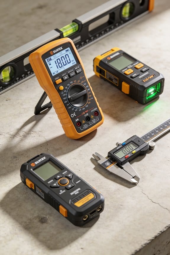
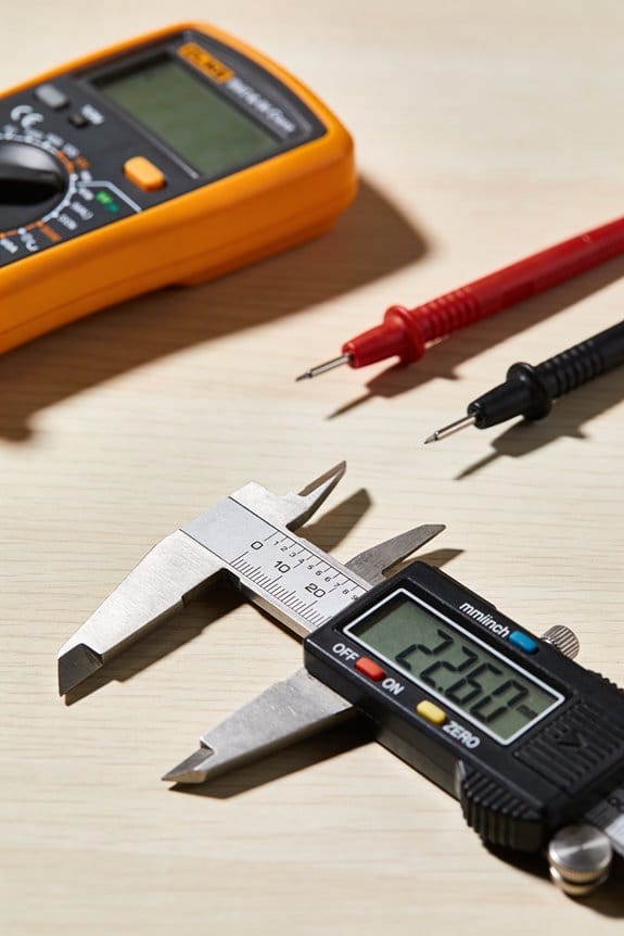
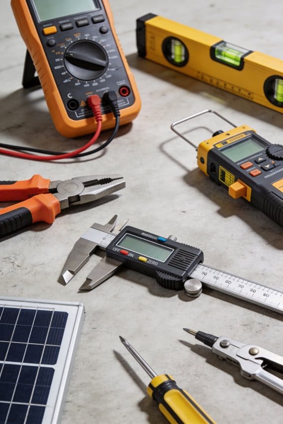
- Use a rugged handheld meter with insulated probes for field work; you’ll avoid shocks and drops. I carry a meter rated CAT III 600 V in a nylon case and replace probes every two years.
Before you start testing, know this: continuity, diode, and capacitance checks find common faults fast. One concrete example: on a garage door opener, a quick continuity test across the limit switch (step 1 below) tells you whether the switch is open or only the motor is stuck.
Steps for a basic component check:
- Turn power off and discharge capacitors.
- Set the meter to continuity or resistance.
- Touch probes across the component leads.
- Read the display — near zero ohms means closed, OL means open.
Logging, auto-ranging, and hands-free modes matter because intermittent faults are hard to catch; you need recorded numbers, not memories. On a machine that stalls every 10 minutes, enable logging and let the meter record during one full cycle so you can correlate spikes in current to the stall.
– Keep operation simple: most DMMs use the same dial and two probes, so you can train someone in under 10 minutes. I taught an apprentice to measure voltage, resistance, and continuity in a single 8-minute demo.
Multimeter Basics and Safety: What to Know First
Before you start using a multimeter, you need to know one key thing: a small fault can give you a wrong reading or a shock.
I check the meter’s insulation and probes before any task. First, look for cracks or cuts in the casing and rubber probe jackets; if you see a nick wider than 1 mm, replace the probe. Second, tug the probe leads gently—if the connection wiggles, swap them out. Example: once I found a hairline crack near the input jack after a drop; replacing the lead stopped intermittent readings during a house wiring check.
Why this matters: a damaged lead can arc under load and hurt you.
Before you measure a live circuit, confirm the auto-range and functions work. Plug the probes into a known 9 V battery, set the meter to DC volts, and verify it reads 9.0–9.5 V; if the readout jumps more than 0.2 V, service the meter. Example: on a job, I caught a meter that auto-ranged slowly and gave fluctuating values while troubleshooting a car alternator; swapping meters saved hours.
When you test resistance, you must disconnect power first. Otherwise, the applied voltage will damage the meter and give garbage readings. Step-by-step:
- Turn the circuit breaker off or remove the component from the circuit.
- Discharge capacitors by shorting through a resistor (10 kΩ, 2 W) if the part held charge.
- Set the meter to the resistance range and zero/short the leads if your meter supports it.

Wear personal protective gear on live work because a single slip can injure you. Put on insulated gloves rated for the expected voltage (e.g., Class 0 for up to 1,000 V), safety glasses, and non-conductive footwear. Example: I wore Class 2 gloves while testing a 480 V panel; a dropped spanner would have been disastrous without them.
Follow manufacturer guidance on battery maintenance since low batteries cause inaccurate or blank readings. Replace cells when the meter warns (low-battery icon) or every 12 months if you use it often. Store spare batteries in a sealed bag and keep the meter in a dry, padded case at room temperature (10–25°C) to preserve seals and accuracy. Example: a contractor I know kept his meter in a damp van and saw the rubber keypad delaminate within six months; a padded case would have helped.
Final quick checklist you can use before any job:
- Visual inspection of casing and probes.
- Tug test on leads and probe tips.
- 9 V battery check for voltage accuracy.
- Disconnect power for resistance checks; discharge capacitors with a 10 kΩ resistor.
- Wear rated gloves and eye protection for live work.
- Replace batteries on low-battery warning or yearly.
- Store the meter in a dry, padded case at 10–25°C.
Keep this checklist on a sticky note in your toolbox and follow it every time.
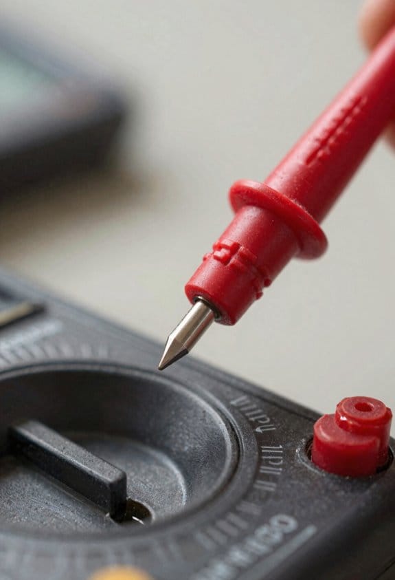
How to Use a Multimeter to Test Continuity
Before you test continuity, know why it matters: it tells you whether a wire or connection will let current flow so you can find breaks quickly.
Here’s what to do, step by step:
- Turn your multimeter on and set it to the continuity symbol (often a diode icon or sound wave).
- Confirm the meter’s audible function by touching the probes together; you should hear a steady beep and see a near-zero reading like 0.0–0.5 Ω.
- Remove power from the circuit—unplug the device or disconnect the battery—because testing on a live circuit can damage the meter or give false readings.
- Place one probe on each end of the wire or across the component you want to test; if you hear the tone or see a reading close to zero, the connection is good.
- If you get no tone and the resistance reads high or OL (open loop), there’s a break or high-resistance joint somewhere.
Example: testing a lamp cord — unplug the lamp, set the meter to continuity, touch one probe to the plug’s hot blade and the other to the socket contact inside the lamp; no beep means the cord or switch is open.
Keep your probes and leads in good shape because worn insulation or corroded tips cause bad readings.
Clean probe tips with fine sandpaper or a contact cleaner and replace cracked leads; a glossy metal tip gives reliable contact.
If you want extra certainty, use these troubleshooting steps:
- Test continuity across the switch while toggling it; a working switch beeps when closed and shows OL when open.
- Check connectors and crimp joints by probing both sides of the terminal; a high resistance reading (over 1–2 Ω in low-voltage hobby circuits) means the joint needs redoing.
- For long wires, test in sections to narrow down the break.
Example: diagnosing a string of holiday lights — unplug the string, test from plug to first bulb, then from bulb to bulb until the tone stops; that bulb or its socket is the likely fault.
Final tip: always start with a probe-to-probe self-check each time you use the meter; if you don’t hear the beep when probes touch, replace the battery or meter.
Recommended Products

Simplifies Pro optical power meter with single and Multimode light sources measures optical power and loss; Transmits 850/1300 nm Multimode wavelengths and 1310/ 1550 single mode wavelengths
Your unit is calibrated prior to shipment with a new nist-traceable calibration Certificate with data

CUSTOMER SERVICE- Micsig has been leading the charge in oscilloscope and oscilloscope probe innovation for years. If you have any questions about Micsig oscilloscope, feel free to reach out. We’ve got you covered with easy EXCHANGE or REFUNDS.
Measure Outlet and Appliance Voltage Safely
Before you start, you need to know one quick reason this matters: a wrong contact or wrong range can kill you or fry equipment. Think of checking an outlet like checking blood pressure — a steady, correct reading tells you the circuit is healthy.
1) Why set the meter and wear gloves
- Why it matters: wrong meter settings can short the circuit or give false readings.
- Real example: I once set my meter to ohms and touched a live plug; it popped the fuse.
- Steps:
- Set your multimeter to an AC voltage range that’s higher than the expected voltage — for U.S. household work choose 200 VAC if your meter has that range.
- Insert the black probe into the COM jack and the red probe into the V jack.
- Put on certified insulated gloves rated for at least 1000 V if you’ll touch exposed contacts.
- Keep your fingers behind the probe guards at all times.
2) How to probe a standard U.S. outlet safely
- Why it matters: a consistent method avoids surprises and gives a reliable reading.
- Real example: you’re replacing a wall plate and want to confirm the circuit is live before touching wires; you’ll read about 120 volts if it’s normal.
- Steps:
- Stand on a dry, non-conductive surface and don’t touch grounded objects while probing.
- Insert the black probe into the neutral slot (the larger, left slot) and the red probe into the hot slot (the smaller, right slot).
- Keep both probes steady and fingers behind the guards; read the display only after the digits stop changing.
- Expect roughly 120 VAC; if you get 0 V, the circuit may be off; if you get around 240 V, you may be on a multi-wire branch or misidentified slots.
3) What to do if readings are unstable or unexpected
- Why it matters: unstable readings can signal loose wiring or a dangerous fault that needs de-energizing.
- Real example: you see the meter jumping between 110 V and 140 V while a hair dryer runs in the same room; that indicates a poor neutral or heavy load imbalance.
- Steps:
- Stop and remove the probes immediately if the reading fluctuates wildly or the meter beeps for overload.
- Turn off the circuit at the breaker and lock it out if possible.
- Inspect the receptacle and wiring visually for loose connections, charred insulation, or backstabbed wires.
- Only re-energize and retest after you fix obvious faults or call a licensed electrician for anything beyond basic tightening.
4) Quick troubleshooting checklist
- Why it matters: a short checklist keeps you safe and saves time.
- Real example: before installing a new dishwasher you run the checklist and catch a half-open breaker that would have given intermittent power.
- Steps:
- Meter set to AC volts and probes in correct jacks.
- Gloves on, dry footing, fingers behind probe guards.
- Black to neutral, red to hot for outlet checks.
- Read stable value ~120 VAC for single-phase U.S. outlets.
- If unstable or unexpected, de-energize and inspect.
Follow those steps and you’ll get reliable readings while keeping yourself safe.
Recommended Products

ASTM F1505 CERTIFIED: Ratchet and socket set built with three-part insulation and rated for use on energized equipment up to 1000V, providing critical visual safety feedback

ELECTRICAL SAFETY GLOVES: Insulating gloves are ideal for lineman work, electrical contractors, field service work and high-voltage machine operators.

KIT INCLUDES: 1 pair of 14" Class 2 rubber voltage insulating gloves; 1 pair of Enespro FR knit gloves; 1 Pair of 10" leather protectors for gloves; glove bag for easy storage
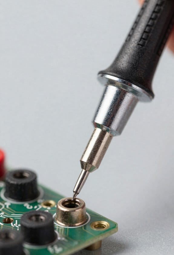
Test Resistance and Components Without Damage
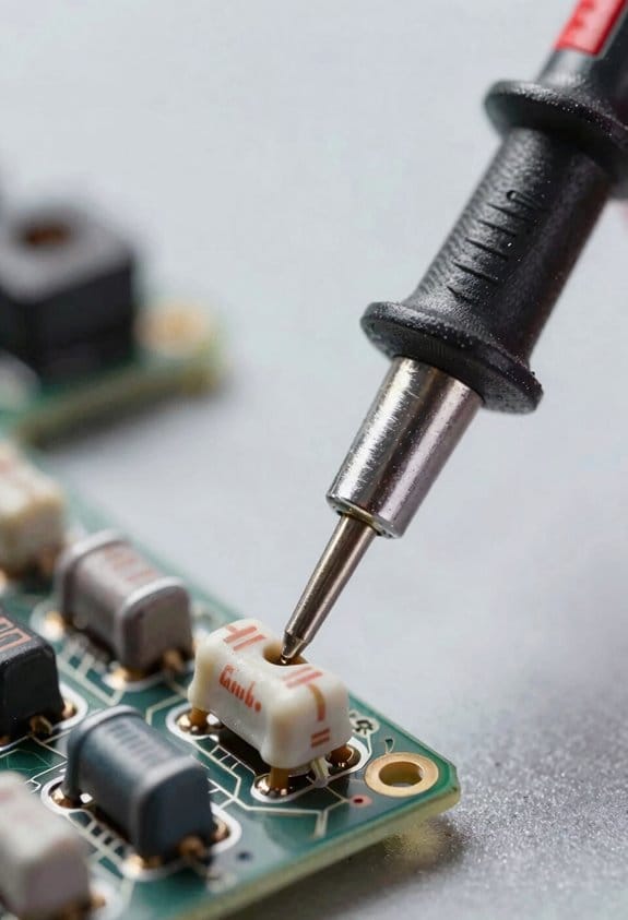
Before you test resistance, you need to know why it matters: a live circuit will give wrong readings and can damage your meter.
1) Remove power and isolate the part
- Why: your meter applies voltage and current, so any live voltage or parallel path will skew the reading.
- Example: when measuring a resistor on a guitar pedal, unplug the pedal and lift one leg of the resistor from the PCB so the meter sees only that resistor.
- Steps:
- Turn the device off and unplug it.
- Discharge stored energy by shorting large caps with a resistor (10 kΩ, 1 W) for at least 30 seconds.
- Lift one lead of the component with soldering iron if it’s soldered to a board.
– Tip: use a 10 kΩ/1 W resistor across a discharged capacitor to keep it safe.
Before you measure, confirm your meter and probes are set correctly so you don’t get a bad reading.
2) Set your meter and probe correctly
- Why: wrong jacks or range will produce garbage or no reading.
- Example: on a typical handheld multimeter, the black lead goes to COM and the red to the jack labelled Ω or V/Ω.
- Steps:
- Insert black probe into COM and red probe into Ω (or V/Ω) jack.
- Select an appropriate resistance range (for auto-ranging meters, just select Ω).
- Zero the meter if it has a relative function by touching the probes together and pressing REL.
– Tip: if your meter has a continuity buzzer, use that for quick checks under 50 Ω.
Before you interpret a number, understand how the meter measures resistance and what can fool it.
3) Recognize stray paths and parallel components
- Why: parallel components make resistors read lower than they really are.
- Example: a resistor on a board can read 200 Ω because a diode in parallel conducts a bit, even though the resistor is 1 kΩ.
- Steps:
- Visually inspect the circuit for other parts tied to the node you’re testing.
- If suspicious, remove one leg of the component or lift it from the board.
- Re-measure after isolation to confirm the true value.
– Tip: note polarity-sensitive parts like diodes and electrolytic caps that can create misleading paths.
Before touching anything live, follow energized-circuit rules so you don’t damage gear or yourself.
4) Never switch to resistance on a live circuit
- Why: the meter will inject current and could short bias networks or blow fuses.
- Example: someone once ruined a sensitive audio preamp by switching to Ω while the unit was powered, causing a DC offset to damage an input stage.
- Steps:
- Always power down and unplug before switching to the Ω setting.
- If you must measure on a powered board, measure voltage only, not resistance.
- Use an isolation transformer or proper bench tools for powered testing.
– Tip: wear eye protection when working on circuits with stored energy.
Before probing capacitors, you must discharge them so you won’t get shocked or damage the meter.
5) Discharge capacitors safely
- Why: charged caps can give a large current that damages your meter or shocks you.
- Example: old tube amplifier filter caps can hold 400 V; shorting them with a screwdriver is dangerous.
- Steps:
- Use a resistor (10 kΩ–100 kΩ, 2 W depending on capacitance) across the capacitor terminals.
- Hold with insulated pliers and measure voltage with a voltmeter until it reads near 0 V.
- Short only after the resistor brings the voltage down if you must use a shorting tool.
– Tip: for high-voltage caps use at least a 5 W resistor and appropriate insulated test leads.
Before concluding, make sure your readings are stable and repeatable so you can trust your result.
6) Verify stable readings
- Why: fluctuating or inconsistent numbers mean a bad connection or a parallel path.
- Example: if your ohmmeter reads 2.05 kΩ, then 1.87 kΩ, then 2.10 kΩ, your probe contact is poor or the component is temperature-sensitive.
- Steps:
- Clean contact points and press probes firmly.
- Wait 2–5 seconds for the meter to settle and watch for drift.
- Repeat the measurement twice; if both readings agree within 5%, accept the value.
– Tip: record the values and the meter range for future reference.
Final safety reminders
- Always disconnect power, isolate the component, and discharge capacitors before switching to Ω. (This is non-negotiable.)
- Use the correct probe jacks and range, and confirm readings by repeating them.
Recommended Products

High-voltage digital megohmmeter has preset and adjustable test voltages for measuring insulation resistance, and also measures leakage current to 2 milliamperes (mA) and capacitance to 20 microfarads

Includes a Fluke 1587 FC 2-in-1 Insulation DMM, Fluke i400 Current Clamp, and a Fluke 62 Max+ Infrared Thermometer

Simulates the presence of an electrical vehicle to test the functionality and safety of an electric vehicle AC charging station.
Common Mistakes and Troubleshooting Multimeter Readings
If you’ve ever misread a meter and blamed the part, this is why.
Why it matters: bad readings waste time and can lead you to replace perfectly good parts. A common case: you measure a resistor on a board and get nonsense because other components are still connected.
1) Why probes and contact matter
Why it matters: poor contact gives unstable or high readings that change when you breathe on the probe. For example, testing a headlight connector on a car with corroded terminals can jump between 0.5 Ω and 5 Ω.
- Clean the contacts with a wire brush or contact cleaner.
- Press the probes firmly and hold for three seconds while you read the display.
- Wiggle the wire at the connector — if the value jumps, replace the lead.
If the reading still varies by more than 10%, swap to a known-good lead.
2) Why battery and meter mode matter
Why it matters: a low meter battery or wrong mode can give wildly wrong voltage or resistance numbers that lead you astray. I once saw a 9 V battery read 7.1 V because the meter was set to the mA jack.
- Check the battery voltage on the meter’s battery test jack; replace if below 6.5 V for a 9 V battery or below 3.6 V for a Li-ion pack.
- Confirm the selector dial: use V for voltage, Ω for resistance, and A for current.
- Verify you’re in the right input jack: voltage and resistance go to the common (COM) and V/Ω jack; current often uses a separate mA or 10 A jack.
If you accidentally measure a live circuit in Ω mode, you can damage the meter.
3) Why zero and calibration checks matter
Why it matters: small offsets ruin sensitive measurements like low milliohm or microvolt tests. For instance, measuring a shunt for an amplifier can be off by 0.2 mΩ without zeroing.
- For resistance, short the probes and press the meter’s zero or relative (REL) function; note the offset shown.
- For sensitive voltage or differential measurements, use the REL function with a shorted input or follow the meter manual to null offsets.
- Every month, measure a calibrated reference resistor or a fresh AA battery (1.5 V) to confirm accuracy.
If the reference is off by more than the meter’s specified tolerance, get the meter calibrated or replaced.
4) Why loose connections and wiring layout matter
Why it matters: intermittent wiring or poor layout gives noisy readings or phantom voltages. I once traced a phantom 12 V on a control wire caused by a parallel motor lead tucked next to it.
- Secure all screw terminals and solder joints; torque screws to the recommended spec if given.
- Route test leads away from power cables and high-frequency sources; keep signal leads under 6 inches away from noisy lines when possible.
- Use a short ground clamp or 4-wire (Kelvin) leads for milliohm measurements.
If readings still wander, clip on a ferrite bead or move the leads and see if the noise follows.
5) Why software and wireless interference matter
Why it matters: nearby radios or meter apps can corrupt logged data and timestamps. I’ve seen Bluetooth telemetry drop samples when a smartphone repeatedly scanned for devices.
- Turn off Bluetooth and Wi‑Fi on the meter or phone while logging.
- Update the meter firmware and the app to the latest versions before a long log run.
- If you must log near radios, use a wired connection or record locally to the meter.
If log files show missing samples or repeated timestamps, re-run the test with radios disabled.
6) Why using a reference source matters
Why it matters: verifying accuracy with a known source quickly tells you if the meter or leads are bad. A desk-lab example is using a 1.000 Ω precision resistor and seeing if your meter reads within its spec.
- Keep one or two reference parts: a 1.000 Ω precision resistor, a fresh AA battery, and a 2.000 V reference cell if you do lots of DC work.
- Measure the reference at startup and after any suspicious readings.
- If the reading deviates outside the meter’s tolerance, swap leads and retest; if it still fails, send the meter for calibration or replace it.
If a new meter reads the reference correctly, your old meter or leads are the culprit.
Quick checklist before you trust a reading:
- Clean contacts and press probes for 3 seconds.
- Check meter battery: replace if low.
- Verify selector dial and input jack.
- Zero or REL for sensitive tests.
- Disable Bluetooth/Wi‑Fi when logging.
- Confirm with a known reference.
Follow these steps and you’ll cut troubleshooting time dramatically.
Recommended Products

Used with a multitude of Megger DLROs from 2A to 600A output

OTC's HD Digital Pressure/Temperature Analyzer combines the functions of vacuum, oil pressure, hydraulic system pressure, fuel pressure, trans pressure, compression, and A/C into one tool

SERVICEABLE - This tablet oscilloscope is thin, light, anti-fall, earthquake-resistant, durable and easy to carry. Unique suspension design, hands-free, more convenient to use for you.
Which Multimeter Features Pros and Industries Need
If you’ve ever been handed the wrong tool on a job, this is why.
You need a meter that matches the job because the right tool speeds troubleshooting and reduces risk. For example, when you trace a live control panel at a factory, a meter with high input impedance prevents the meter from loading the circuit and causing false voltage readings.
Why voltage and current range matter: you want accurate readings across the values you encounter. Use a meter with at least 0.5% DC voltage accuracy and a wide DC range up to 1000 V for industrial use; for electronics work you’ll want ranges down to 0.1 mV resolution. If you’re checking motor starters, pick a meter with a 10 A continuous range and a separate mA jack so you don’t blow fuses by plugging into the wrong input.
Why continuity and diode tests matter: they speed basic checks. Look for audible continuity at <30 Ω threshold and a diode test that shows forward voltage in millivolts so you can tell a 0.7 V silicon drop from a 0.2 V Schottky. On an automotive harness, that audible beep quickly tells you which splice is open while you hold the harness in one hand.
How to avoid loading circuits: choose high input impedance and the right range. Steps:
- Check the meter spec sheet for ≥10 MΩ input impedance for DC volts.
- Set the range high enough to avoid overloading; auto-range is okay if it’s fast.
- Confirm readings against a known reference, like a 12.00 V bench supply.
Why selectable current jacks matter: they prevent blown fuses and meter damage. Use the mA jack for microcontroller currents (<200 mA) and the 10 A jack for motors or inrush currents up to 10 A. A real-world example: measuring a running pump drew 6 A, and swapping to the 10 A jack kept the fuse intact.
Why case durability and waterproofing matter: you’ll drop the meter and work in wet sites. Choose IP54 or higher and a rubberized holster with a tilt stand. On a rooftop HVAC call, a splash-resistant meter kept working after a sudden shower.
Why display and auto-ranging matter: clear displays get you readings fast. Pick meters with at least a 6000-count LCD, backlight, and fast auto-ranging that locks within one second. In a dim basement, the backlight and large digits let you read values without moving the probe.
Why low-resistance ohm ranges matter: they find tiny faults. Look for a 0.1 Ω resolution and a four-wire (Kelvin) mode for shunt and low-resistance checks. When you measure a battery cable, Kelvin mode shows joint resistance like 0.012 Ω instead of a misleading 0.2 Ω.
Why thermal imaging or attachments help: they speed non-contact diagnosis. A pocket thermal imager that clips to your meter or phone shows hot spots like a failing bearing or loose lug without touching live parts. On a compressor rack, a thermal snapshot flagged a 60 °C lug that felt only warm by hand.
Why calibration and documented accuracy matter: you may need traceable results for compliance. Get meters calibrated annually with a certificate showing uncertainty; use a lab that provides NIST-traceable calibration. In an ISO audit, that certificate proves your readings meet spec.
Quick checklist you can use before a job:
- Voltage accuracy ≥0.5% and ranges to 1000 V.
- Input impedance ≥10 MΩ.
- Separate mA and 10 A current jacks.
- Continuity beep <30 Ω and diode mV readout.
- 6000-count display with backlight and fast auto-range.
- Low-resistance range 0.1 Ω or Kelvin mode.
- IP54+ housing and rubber holster.
- Optional thermal attachment and annual NIST-traceable calibration.
Pick features based on the work you’ll do, and keep one spare fuse and a set of test leads in your kit.
Recommended Products

◆Automotive Oscilloscope Support 12V & 24V charging/start, Charging Ripple, Cranking Current etc.

Fluke-289V Advanced data logging Multimeter has a large 50,000 count,1/4 VGA display
【MATRIX LCR METER BENCHTOP】Precision digital lcr meter for labo voltage capacitor ground insulation resistance. It adopts 4.3-inch TFT LCD screen, 5-digit test resolution impedance meter instrument, multi-frequency points and 0.1% accuracy to meet the testing needs of various components and parameters.
Frequently Asked Questions
Can a DMM Measure Temperature and How Accurate Is It?
Yes — I can measure temperature using thermocouple adapters or an internal sensor_accuracy reading; I’ll get decent results, often ±0.5–2°C depending on probe type, calibration, and meter quality.
How Do Multimeters Compare to Clamp Meters for Current Measurement?
Measure twice, cut once — I prefer a DMM for precise low-current readings and resistance checks, but an AC clamp’s noncontact convenience wins for high currents; watch resolution limits and accuracy trade-offs when choosing.
Are Auto-Ranging Multimeters Slower Than Manual-Ranging Models?
No — I don’t find auto-ranging multimeters noticeably slower; auto ranging latency is typically minimal, though manual responsiveness can feel faster for rapid scale changes, so I switch to manual when I need instant, consistent readings.
Do Multimeter Batteries Affect Measurement Accuracy Over Time?
Yes — I’ve seen battery degradation cause drifting readings and reduced backlight, and in extreme cases affect input impedance; I’ll replace batteries regularly and verify with a known reference to maintain measurement accuracy over time.
Can Multimeters Safely Test Live Photovoltaic (Solar) Arrays?
Yes—I cautiously test live photovoltaic arrays, but I follow strict isolation protocols and use proper PPE; I often perform insulation testing with rated equipment and never exceed the multimeter’s voltage/current ratings to avoid damage or injury.