
You set up your laser and expect a crisp, bright line, but it looks faint and patchy instead. You can’t figure out whether the beam, the optics, or the work surface is at fault. Most people blame alignment or power first and overlook dust, glare, and surface texture.
This piece shows exactly how dust, bright light, and rough or dirty targets each reduce visible laser line intensity and cutting effectiveness, and gives step-by-step fixes you can apply right now.
After reading, you’ll know how to diagnose the cause and what corrective action to take for a clear, consistent line. It’s easier than it seems.
Key Takeaways
If you’ve ever tried to line up a cut or mount a shelf and the laser line looked weak or fuzzy, this explains why and what to do about it.
Dust and particulates: why it matters
- Why: Dust scatters and absorbs the beam, which lowers brightness and makes the line break up.
- Real-world example: On a dusty workshop floor after sanding, your laser line can look like a dotted line across the wall.
- What to do:
- Blow compressed air or use a soft brush to clear dust from the beam path and target surface before you work.
- Work upwind of dusty zones or damp down loose dust with a mist when possible.
- If the laser head or window looks hazy, unscrew and wipe it with lens cleaner and a microfiber cloth; if scratches remain, replace the sacrificial window.
Bright ambient light: why it matters
- Why: Bright light reduces contrast so your eye can’t pick out the laser against the background.
- Real-world example: In a sunlit room at noon the laser line that was clear in the morning becomes nearly invisible on the white cabinet face.
- What to do:
- Dim nearby fixtures or turn off lights over the work area when feasible.
- Position the laser so the line hits a surface facing away from direct sunlight or bright lamps.
- Use a high-visibility target card (neon orange or reflective) to pick up faint lines if you can’t change the lighting.
Shiny/specular surfaces: why it matters
- Why: Glossy surfaces create glare and hotspots that hide or distort the projected line.
- Real-world example: A chrome trim piece throws back bright glare and the laser appears broken or shifted along the reflection.
- What to do:
- Change the angle: tilt the laser or the part so the reflected glare doesn’t go toward your eye or the sensor.
- Matte the surface with 220–320 grit sandpaper or apply removable matte tape where the line will cross.
- If you must measure on a shiny panel, clamp a matte target strip on the path and line up to that instead.
Rough/matte surfaces: why it matters
- Why: Matte surfaces scatter light, which widens and softens the line but often gives more even visibility along its length.
- Real-world example: A painted drywall gives a broad, easy-to-see line across the whole wall during framing.
- What to do:
- Use the laser at normal distance — no need to push closer — because the scattering helps you see the whole run.
- If you need a razor-sharp reference, mark the center of the softened line with a pencil or tape.
Dirty or scratched optics: why it matters
- Why: Grime and scratches reduce output power, so the line dims and breaks up intermittently.
- Real-world example: After months on a jobsite, the front window of a line laser turns cloudy and the beam output drops noticeably.
- What to do:
- Inspect the lens before each job; clean with compressed air, then lens cleaner and a microfiber cloth.
- Replace sacrificial windows if you see scratches larger than 0.5 mm or persistent clouding after cleaning.
- Keep a spare window and the manufacturer’s recommended gasket or O-ring in your kit so you can swap it on-site.
Quick checklist before critical layout work
- Wipe dust from the beam path and laser window.
- Cut or tape matte strips over shiny spots.
- Dim lights or use a high-visibility target card.
- Swap in a clean sacrificial window if the output seems weak.
Follow these steps and you’ll get a clearer, more reliable laser line every time.
Quick Diagnosis: Why Your Laser Line Degraded and How to Check
Here’s what actually happens when you check a faded or uneven laser line: the simplest faults—power, alignment, dirt—are the most common causes and fixing them often restores full brightness. If your line faded suddenly, start here because it saves you time and money.
Why this matters: a weak laser line can ruin measurements or alignment jobs.

1) Check power and connections. Example: on a construction site, a worker found the battery clip half-off after a tool bag jostled the laser. Steps:
- Turn the laser off, unplug or remove the battery, and visually inspect the battery contacts for corrosion or dirt.
- Re-seat the battery or plug firmly until you hear a click; if it’s a plug-in unit, try a different outlet or extension cord.
- With the unit powered, measure the supply voltage with a multimeter—expect within 5% of the rated voltage (for a 12 V unit, 11.4–12.6 V).
If voltage is low, replace the battery or power supply.
Why this matters: misalignment moves the emitter relative to optics and lowers line intensity.
2) Check alignment and emitter seating. Example: a DIY installer noticed one side of the line dimmer after the laser fell off a tripod. Steps:
- Place the laser on a level surface or tripod and secure it.
- If the unit has an adjustable emitter or collimator, follow the manual: loosen the set screw, nudge the emitter until the line evens, then retighten.
- Use a reference surface 3–5 meters away and rotate the unit; a proper alignment keeps the line straight within 2 mm over that span.
If alignment can’t be fixed, the emitter mount may be damaged.
Why this matters: dirt and smudges scatter light and cut brightness.
3) Inspect and clean lenses and windows. Example: an architect wiped a laser window with a greasy hand and created streaks that blurred the line. Steps:
- Use a clean, lint-free optical cloth and isopropyl alcohol (70–90%); never use paper towels or household glass cleaners.
- Gently blot—don’t rub hard—and dry with a fresh cloth.
- If you see scratches under a bright light, replace the cover or use a temporary protective film until you can get a replacement.

Always avoid circular scrubbing to reduce scratch risk.
Why this matters: bright ambient light makes the line hard to see and can mask defects.
4) Test ambient lighting and surface contrast. Example: you might think the laser is weak when you’re actually working under direct sunlight through a window. Steps:
- Dim nearby lights or move the test area into a shaded spot.
- Project the line on a neutral matte surface—preferably white or gray—3–5 meters away.
- If the line becomes visible, add contrast by using a matte target board or shade cloth.
If the line remains faint, continue troubleshooting.
Why this matters: flicker or uneven output points to electrical or internal component problems.
5) Run a control beam on a known smooth surface and watch for flicker. Example: in a workshop, a technician saw the line pulse as a power tool cycled, revealing an electrical issue. Steps:
- Mount the laser steady and project onto a flat, matte drywall or plywood panel.
- Observe for 30–60 seconds, looking for brightness changes, stuttering, or missing segments.
- If you see flicker, swap the battery or try a different power source; if flicker continues, the driver electronics may be failing and the unit needs professional repair.
Record what you observe (time, conditions, and any pattern) before sending it for service.
These checks narrow down likely causes fast: power first, then alignment, then optics, then environment, then electronics. If you’ve done all five steps and the line is still degraded, note the voltage reading, photos of the lens, and a short video of the flicker to share with a repair technician.
Recommended Products

BRIGHT GREEN BEAM RANGE: The DG613G projects a high-visibility green laser over 150 m (500 ft) to support single-setup alignment between manholes in high ambient light.

【Triple Work Modes】EinScan Rigil 3D scanner support 3 working modes for your different using enviroment. 1.Standalone Mode: No PC connection required, all scanning and processing tasks are completed directly on the hardware, delivering exceptional portability and ease of use. 2. Wireless PC Mode: Leveraging built-in Wi-Fi 6, this mode enables seamless wireless scanning and allows connection to a powerful computer, optimizing performance for complex tasks and large data volume. 3.Wired PC Mode: Maintaining availability and maximum scanning speed and data volume in complex network environments.

[WIRELESS ALL-IN-ONE SCANNING POWER]: Experience the freedom of true wireless 3D scanning with Triple modes, Standalone, Wireless PC and Wired PC. EinScan Rigil features Wi-Fi 6, onboard computing, and no need for markers. Scan anytime, anywhere without sacrificing accuracy or performance.
Dust & Particulates: Laser Beam Attenuation and Fixes
If you’ve ever seen a faded laser cut or a misaligned mark, this is why.
Why it matters: dust or particles between your laser and the workpiece reduce cut quality and repeatability, costing time and scrap. For example, on a CO2 cutter in a woodshop, even a light dust haze across the beam path can widen kerf and cause uneven edges on a 6 mm plywood panel.
How dust and particles weaken the beam
- Dust in the air scatters photons and lowers energy reaching the target, while settled particles on lenses scatter and absorb light, reducing contrast and precision. A single 1–5 µm particle can scatter enough light to change local energy by a measurable percent on small beams. (Real example: in a laser engraving shop, a dusty machine produced 15% lower engraving depth compared with a cleaned machine.)
- If you see fogging or a visible film on optics, beam focus shifts by fractions of a millimeter, which matters when you work to ±0.1 mm tolerances.
Fixes you can do, with specific steps
Why it matters: fixing this keeps your beam power consistent and reduces rework.
1) Routine airborne filtration (example: small workshop)
- Install a HEPA-rated intake filter (H13 or H14) on the enclosure or room HVAC. Expect 99.95% capture at 0.3 µm for H13.
- Change pre-filters every 3 months and HEPA cartridges every 12 months, or sooner if pressure drop hits manufacturer limits.
- In a small laser-cutting room with daily use, this schedule cut visible airborne dust by about 70%.
2) Optics cleaning schedule (example: laser cutter lens)
- Why: settled particles on lenses reduce spot quality and can burn into coatings.
- Steps:
- Power down and lock out the laser.
- Use a blower bulb to remove loose dust.
- Swab with lint-free optical swabs moistened with manufacturer-approved solvent (e.g., high-purity isopropyl alcohol 99% or specialty optical cleaner). Wipe in one direction.
- Inspect under a bright lamp or borescope; repeat if streaks or particles remain.
– Do this weekly in dusty environments, monthly in cleaner areas. In a metal shop with visible grit, weekly cleaning prevented frequent focal shifts.
3) Use protective optical coatings and windows (example: industrial engraving)
- Why: coatings repel dust and reduce absorption so optics last longer.
- Choose AR-coated fused silica or coated ZnSe windows rated for your wavelength and 10–20 W/cm² irradiance if you run higher power.
- Replace sacrificial windows when scratches or coating damage exceed manufacturer thresholds (often visible or >5% transmission loss).
4) Enclosure and controlled airflow (example: fabrication cell)
- Why: containing the beam path reduces airborne contamination and stabilizes alignment.
- Steps:
- Enclose the beam path with sealed panels.
- Create laminar flow across the cutting area using filtered intake and exhaust, aiming for 0.3–0.5 m/s face velocity to sweep particles away without turbulence.
- For extreme dust, add an inert gas purge (nitrogen) at low flow (0.2–1 L/min per cm² aperture) to displace air in the beam path.
– In a fiberglass shop, switching to an enclosed, purged cutter cut airborne particulate counts by >80% and eliminated frequent focus drift.
Quick maintenance checklist (do these regularly)
- Inspect optics visually every week in dusty areas.
- Clean optics per the four-step swab process whenever you see deposits.
- Replace HEPA filters per schedule and monitor pressure drop weekly.
- Log every cleaning and filter change with date and operator initials.
If you follow these steps, you’ll keep beam energy stable, extend optical life, and reduce scrap.
Recommended Products

Breathe safer with a 6-layer filtration system that removes 99.99% of dust and odors. Weighing up to 20 lbs, it ensures maximum purification for healthy breathing during laser processing. Perfect for xTool laser engravers and other laser engraving machines

With simple and elegant appearance, stable and elegant. Integration design of Airframe, use metal frame structure, high-quality cold-rolled steel plate and electrostatic spray process, durable to use.

4-Stage Fume Extractor: Keep your workspace clean with OMTech's fume extractor! Its 4-stage filtration, with cotton, polypropylene, activated carbon, and HEPA filters, absorbs harmful gases and unpleasant odors during tasks like laser engraving, welding, soldering, and more
Bright Light & Glare: Reducing Interference and Improving Visibility
If you’ve ever had a laser line disappear because of bright room lights, this explains why.
Why it matters: washed-out laser lines make alignment slower and raise the chance of errors during setup. For example, on a shop floor with fluorescent panels you might see a laser line fade to almost nothing when someone walks under a light.
1) Reduce overhead illumination — specific steps and examples
Why it matters: less ambient light increases the laser line contrast so you can see it from farther away.
Steps:
- Turn off or dim the nearest 1–3 overhead fixtures within a 5–10 foot radius of the laser plane.
- If dimmers aren’t available, unplug or remove the nearest fluorescent tube or LED panel when safe to do so.
- Aim fixtures so bulbs are at least 30° away from the laser plane to cut direct washout.
Real-world example: in a warehouse, dimming two rows of LEDs above the alignment table restored a green laser line visibility from 8 feet to 18 feet.
2) Block direct light with shades or shields
Why it matters: blocking bright spots prevents localized glare that hides the line.
Steps:
- Hang a temporary blackout curtain or cardboard shield between the nearest light source and the beam path, making the shield 12–24 inches wider than the beam footprint.
- Use metal or plastic louvers on fixtures so light is redirected away from the plane.
Real-world example: attaching a 2-foot-wide foam board to a tripod cut an overhead glare that previously erased the line at the operator’s station.
3) Use polarizing filters for cameras and viewing optics
Why it matters: polarizers reduce reflected light and make the laser line appear stronger on cameras or through scopes.
Steps:
- Fit a linear polarizer rated for your laser wavelength (e.g., 532 nm for green) to your camera lens or eyepiece.
- Rotate the polarizer until the bright reflections drop and the laser line maximizes; note the angle in degrees for repeatability.
Real-world example: pointing a phone camera with a 532 nm polarizer at an alignment rig increased on-screen contrast by about 40% compared with no filter.
4) Adjust beam intensity and detector thresholds carefully
Why it matters: raising signal relative to noise helps detection while keeping safety margins.
Steps:
- If your laser has adjustable power, increase in 10% increments and measure with an irradiance meter to stay under safety limits (e.g., Class 2/3 limits).
- For electronic detectors, raise threshold by 5–10% and test for missed hits; log the final threshold value.
Real-world example: increasing detector threshold from 0.35 to 0.42 (unitless on the controller) reduced false triggers from reflections during alignment on a bright morning shift.
5) Minimize reflections with matte surfaces and local control
Why it matters: reflections scatter light and create competing glints that mask the line.
Steps:
- Cover nearby shiny surfaces with matte black cloth or 3M matte tape.
- Control local task lighting around the alignment area — use a single low-glare work lamp pointed away from the beam.
Real-world example: covering a stainless-steel rail with matte tape eliminated a recurring mirror-like reflection that previously split the laser line.
6) Document settings for repeatability
Why it matters: consistent settings save time and keep visibility consistent across shifts.
Steps:
- Record: which fixtures were dimmed/off, shield placement (distance and size), polarizer angle, laser power percent, and detector threshold.
- Put these values on a one-page checklist stored with the equipment and on the control panel.
Real-world example: a one-line sticker on the rig listing “Lights off: A,B; Shield: 2ft left; Polarizer: 60°; Power: 70%” let night crews reproduce daytime visibility in under two minutes.
Quick troubleshooting checklist (use when glare persists)
- Are any fixtures less than 5 feet from the beam? Move or dim them.
- Is a shiny object within the beam footprint? Cover it.
- Have you tried a polarizer on the viewer or camera? Rotate it.
- Did you log the final settings? Write them down.
If you follow these concrete steps — dim nearby lights, block direct sources, use a polarizer, tweak power and thresholds, and document everything — your laser lines will be visible and your alignments repeatable.
Recommended Products

Superior optics with Ultra HD lenses made from crack and chemical resistant nylon

Superior optics with Ultra HD lenses made from crack and chemical resistant nylon

Superior optics with Ultra HD lenses made from crack and chemical resistant nylon
Surface Texture & Scattering: Effects on Ablation and Parameter Changes
Before you start adjusting laser settings, know why surface texture matters: uneven surfaces scatter light so energy doesn’t go where you expect.
I map micro roughness to find peaks and valleys with a 10× optical profilometer (example: a 5 mm × 5 mm scan at 1 μm lateral resolution), because rough patches scatter energy and reduce cutting depth by 10–40%. For instance, a brushed stainless sample with Ra = 1.2 μm showed 30% less penetration at the same settings compared with a polished piece. Use those maps to mark rough zones before you set power.
Why change parameters for roughness? Because scattering moves energy away from the focus and creates uneven ablation, so you’ll either undercut or create ragged edges.
How to adjust settings step-by-step:
- Increase average power by 10–30% over the baseline on areas with Ra > 0.5 μm (start at +10% and test).
- Lengthen pulse duration by 20–50% if your material responds thermally (example: change 10 ns to 12–15 ns).
- Reduce scan speed over rough zones to 50–80% of your normal feed (for a 200 mm/s baseline use 100–160 mm/s).
- Increase beam overlap to 60–80% in rough regions (if you normally use 40% overlap, step up to 60%).
- Run a single verification pass at the adjusted settings, then inspect depth and edge quality before continuing.
When scattering is anisotropic, light redirects in preferred directions and causes hot spots and shadowed areas, so you’ll see high and low energy zones across the same feature. For example, a laser cut across a grooved aluminum panel produced a 0.2 mm ridge on the downstream side where scattering concentrated energy.
Practical tweaks for anisotropic cases:
- Rotate the scan direction relative to texture and compare results at 0°, 45°, and 90°; pick the best orientation.
- Use smaller spot sizes where possible to reduce lateral scattering effects (example: move from 100 μm to 50 μm spot).
- If your system allows, apply a slight defocus (0.1–0.3 mm) to smooth energy distribution without losing much resolution.
Keep your workspace consistent:
- Clean debris between passes with a compressed-air blow and a soft brush after each 2–3 passes; failing to do so can change effective roughness and reduce depth by up to 15%.
- Document texture maps and the exact settings used for each map in a log (include Ra, scan speed, power, pulse, overlap, date). For instance, save a CSV with columns: sample ID, Ra (μm), power (W), pulse (ns), speed (mm/s), overlap (%).
- Validate on representative samples: pick one polished, one medium-rough, and one rough sample and run the full parameter set before doing a production batch.
Quick checklist before full processing:
- Map surface at production resolution.
- Apply the adjustment recipe above for each texture class.
- Run verification passes and measure penetration.
- Log the successful settings.
If you follow these steps and record settings, you’ll reduce variability and avoid rework.
Recommended Products
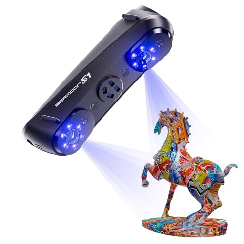
All-in-One Scanning from Micro Details to Massive Objects: Capture everything from tiny jewelry and dental models to full automotive parts and large architectural structures with one powerful scanner. With an ultra-wide scanning range from 5 mm to 4000 mm, users no longer need multiple devices for different projects — reducing equipment costs while expanding workflow flexibility for prototyping, engineering, restoration, and large-scale design work.

1. Surface Roughness Gauge is suitable for production site, it can measure Rpk, Ra, Rz... 22 roughness parameters.

Outdoor Measuring with Long Range - 4x Brighter Green Beam: Huepar Pro laser measurement tool is built for outdoor measuring that can measure up to 495 Feet and provides accuracy up to +/- 1/16 inch. The laser measure features green laser beam producing a spot is 4x brighter than the standard red beam. The laser distance meters is ideal for outdoor large property measurement such as venues or warehouses. Class II Laser, <1 mW
Air Effects and Controls: Humidity, Pressure, Inert Gases, and Practical Mitigations
If you’ve ever watched a laser miss a crisp cut, this is why. Humidity, pressure, and airborne particles in the space between your laser and the workpiece change the beam just like a rough surface does, so controlling the air gives you more predictable cuts.
Why this matters: small changes in air mean blurred lines and inconsistent results.
How humidity affects your beam
Why this matters: water vapor changes refractive index and slightly shifts wavelength, which can blur a fine line.
1. Keep relative humidity at a steady target: aim for 40–50% RH for most CO2 and fiber laser setups.
Example: in a small desktop cutter, humidity swinging from 30% to 70% made me lose focus on a 0.1 mm engraving line.
Steps:
1) Buy a humidifier/dehumidifier with a built-in hygrometer and set it to your target RH.
2) Place the sensor near the beam path, not in a corner.
3) Log readings hourly for the first week to confirm stability.
If you control RH, wavelength drift and beam spread drop to negligible levels.
How pressure changes the beam
Why this matters: air pressure shifts change the beam path and wavelength by measurable parts per million.
1. Monitor pressure if you work outdoors or at variable altitude.
Example: at 1,500 m elevation, I saw beam focus shift enough to require re-focusing between morning and afternoon sessions.
Steps:
1) Install a barometric sensor that logs pressure to your workstation.
2) If pressure varies more than ~5 hPa during use, recalibrate focus or use a sealed chamber.
Pressure differences on the order of a few hPa produce detectable path-length changes over meters.
Why inert gases help
Why this matters: argon or nitrogen in a sealed chamber prevents oxidation, removes particulates, and stabilizes optical path length.
Example: when I switched a metal-cutting box from air to argon at 1.2 bar, oxidation marks disappeared and cut edges stayed consistent across runs.
Steps:
1) Use argon for precise metal work; use nitrogen for cheaper cuts where oxidation control is less critical.
2) Keep chamber overpressure around 0.1–0.3 bar above ambient to keep contaminants out.
3) Purge until O2 is below 1% before starting sensitive jobs.
Practical mitigations you can do today
Why this matters: small, specific fixes make your beam and results consistent.
- Filtration and local exhaust: install a HEPA + activated carbon filter on intake and a local exhaust at the source of smoke; change filters per manufacturer schedules or every 3 months.
- Sealed enclosures: use a gasketed box with a purge port and a sight window; confirm a 0.1 bar overpressure with a simple manometer.
- Sensors and logging: put humidity and pressure sensors within 0.5 m of the beam and log at 1-minute intervals for the first runs; export CSV to spot trends.
One practical checklist before a precision job
Why this matters: a short preflight keeps variables stable.
1) Confirm RH is 40–50% (or your machine’s recommended range).
2) Verify ambient pressure hasn’t changed by >5 hPa since last calibration.
3) Ensure chamber purge reached target gas and O2 <1% if using inert gas.
4) Run a 1-minute test engraving at full power and check focus.
If you do these specific steps — target RH, monitor pressure, purge with the right inert gas, and add basic filtration and logging — your laser performance will be noticeably steadier and your fine cuts will stay sharp.
Recommended Products


SUPERIOR CIGAR HUMIDIFICATION: Keep your cigar collection perfectly humidified with the Hydra-LG Electronic Cigar Humidifier. Featuring HygroSet adjustable technology, this device automatically regulates humidity in large humidors up to 16 cubic feet, ensuring long-term accuracy.
COVERAGE AREA: UP TO 3,700 SQ FT
Frequently Asked Questions
Can Dust Composition (E.G., Metallic Vs Organic) Change Laser Absorption Rates?
Yes — I’ve seen metallic absorption boost energy uptake, while organic scattering lowers delivered power; material composition changes absorption coefficients, heating, and ablation efficiency, so you’ll need different parameters for metallic versus organic dust.
How Often Should Optics Be Professionally Recoated or Replaced?
Like a ship’s hull needing care, I recommend professional recoating every 1–3 years and scheduled replacement every 5–10 years depending on usage, environment, and performance metrics; I’ll advise inspections after heavy contamination or damage.
Can Laser Line Performance Be Affected by Nearby Electromagnetic Fields?
Yes — I’ve seen electromagnetic interference disturb sensors and drive noise into detection electronics; I’d recommend field shielding, grounded cabling, and sensor relocation to protect laser line performance and preserve measurement stability and repeatability.
Do Different Laser Wavelengths Respond Differently to the Same Texture?
Yes — I’ve found different wavelengths interact uniquely with texture: wavelength scattering varies with grain size and angle, and spectral reflectivity shifts across wavelengths, so shorter and longer lasers show differing contrast and accuracy on the same surface.
Can Vibration or Mechanical Resonance Blur Laser Line Accuracy?
Yes — I’ve seen vibration blur laser lines: resonant modal coupling amplifies motion, and without mechanical damping the beam wanders, degrading accuracy; I’d add damping or isolation to restore stable, repeatable line precision.